Draper canvas with a shaped edge

a shaped edge and canvas technology, applied in the field of canvas with a shaped edge, can solve the problems of not being adopted and the arrangement has not been successful

Active Publication Date: 2012-10-23
MACDON INDS +1
View PDF28 Cites 42 Cited by
  • Summary
  • Abstract
  • Description
  • Claims
  • Application Information

AI Technical Summary

Benefits of technology

[0010]It is one object of the invention to provide a further design of header and particularly the draper canvas therefore which can assist in providing a seal between the canvas and the cutter bar.

Problems solved by technology

This arrangement has not been successful and has not been adopted since it failed to provide the expected improvements over the Talbot and Fox arrangement.

Method used


Image

  • Draper canvas with a shaped edge
  • Draper canvas with a shaped edge
  • Draper canvas with a shaped edge

Examples


Embodiment Construction

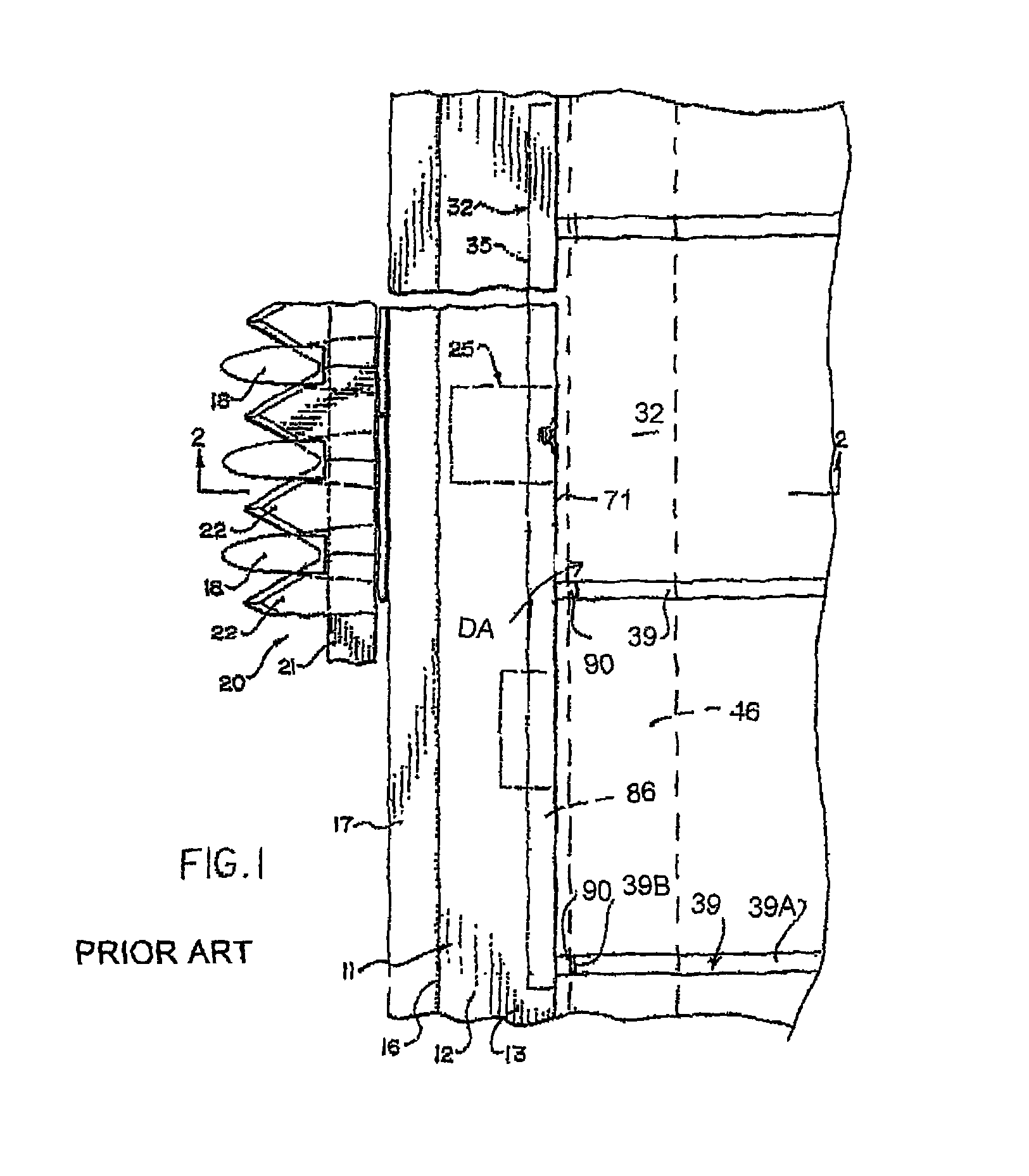
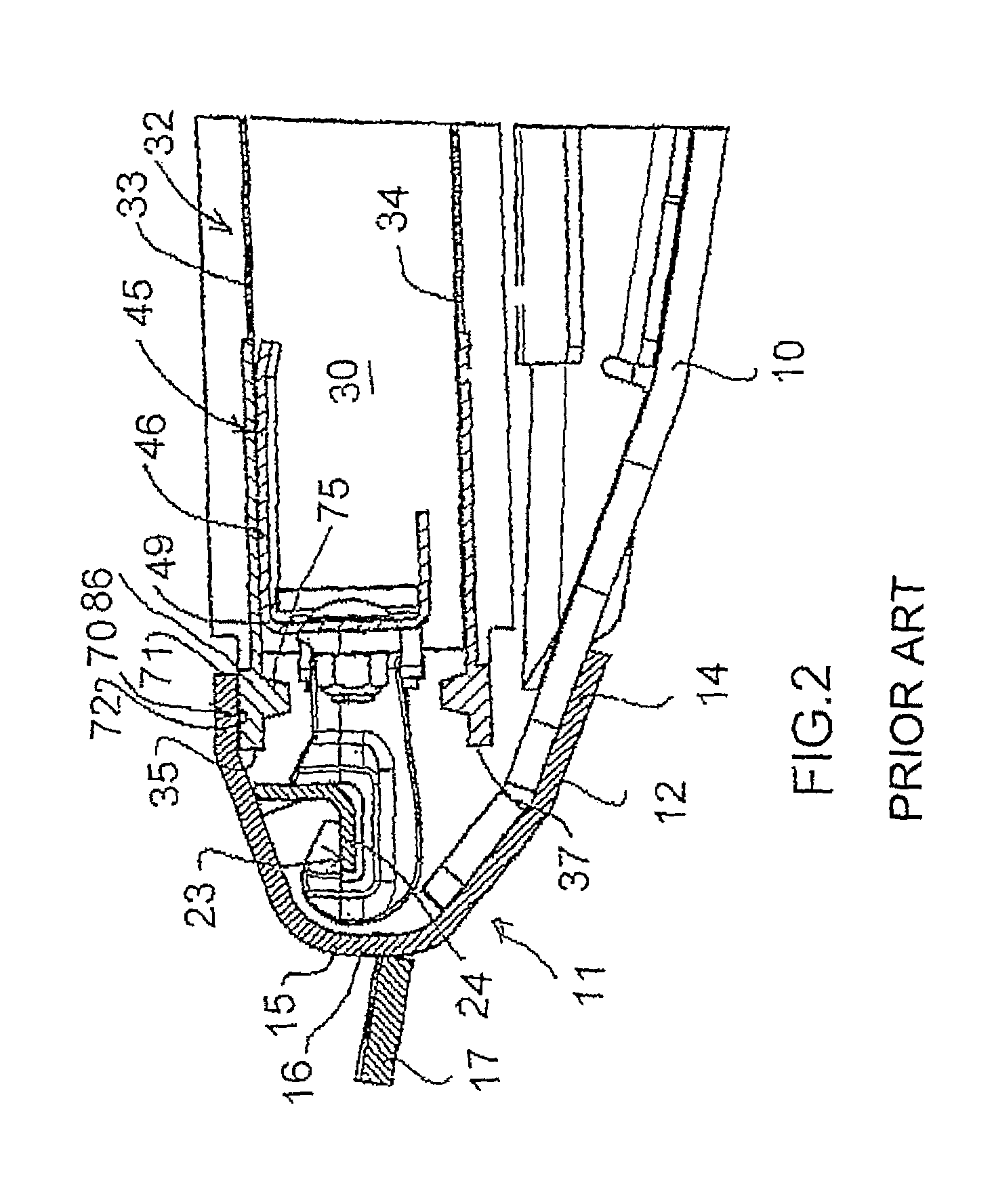
[0046]The following description is taken from the above prior art patent. Only those parts of the header which are of importance to the present invention are shown in the above figures of the present application and the remaining parts of the header including the frame structure, drives, ground wheels and the like are omitted as these will be well known to one skilled in the art.

[0047]The header therefore comprises a frame, one element of which is indicated at 10 in the form of a beam extending horizontally and forwardly from a rear support frame structure (not shown) to a cutter bar assembly generally indicated at 11 for support of that cutter bar assembly. The beam 10 forms one of a plurality of such beams arranged at spaced positions along the length of the header frame so as to support the cutter bar assembly 11 as an elongate structure across the front edge of the header.

[0048]The cutter bar comprises a generally C-shaped beam 12 which provides structural support for the cutter...


PUM


Abstract

A crop harvesting header with a cutter bar and a draper assembly has a draper canvas with an edge portion across a front edge to cooperate with a rearwardly projecting element of the cutter bar extending over the upper run of the draper canvas to engage the upper surface of the edge portion to form a seal to inhibit entry of dirt or crop between the cutter bar and the draper canvas. The edge portion of the canvas is thicker and is canted upwardly at an angle of the order of 10 to 20 degrees. There is also provided a bead on the canvas on the surface opposite the strip within the width of the strip. The arrangement can be symmetrical with a strip at each of the front and rear edges spanned by the slats extending between them.

Description

[0001]This invention relates to a header for cutting and transporting a standing crop with a transverse leading cutter bar and particularly to an arrangement which provides a seal between a front edge of a draper canvas and an element of the cutter bar and to a draper canvas designed for use with the header.BACKGROUND OF THE INVENTION[0002]Draper headers generally include a header frame, an elongate cutter bar along a front edge of the frame including a cutter bar beam which carries a plurality of knife guards for guiding reciprocating movement of a sickle knife across a front edge of the cutter bar. On the header is also mounted a draper assembly including a first and second draper guide roller each arranged at a respective end of the draper assembly spaced apart along the cutter bar with an axis of each roller extending substantially at right angles to the cutter bar, a draper canvas forming a continuous loop of flexible material wrapped around the rollers so as to define a front ...

Claims


Application Information

Patent Timeline
Patent Type & Authority Patents(United States)
IPC IPC(8): A01D43/00
CPCA01D61/002
Inventor CORMIER, DANIELMARLER, RONALD L.
Owner MACDON INDS
Why Eureka
Try Eureka