Cathode

a cathode and main electrode technology, applied in the field of cathodes, can solve the problems of poor cutoff capability and cutoff capability that can only be achieved with a higher cutoff voltage, and achieve the effect of good cutoff capability

Active Publication Date: 2012-10-23
SIEMENS HEALTHCARE GMBH
View PDF10 Cites 9 Cited by
  • Summary
  • Abstract
  • Description
  • Claims
  • Application Information

AI Technical Summary

Benefits of technology

[0008]An object of the present invention is to provide a cathode with a good cutoff capability.
[0011]By fashioning the surface emitter as a parallel surface emitter with at least two emitter surfaces spaced apart from one another, and by feeding at least one electrically conductive cutoff electrode (that is galvanically separated from the surface emitter) to the surface emitter, the disadvantage of a poorer cutoff capability, or a cutoff capability that can only be achieved with a higher cutoff voltage, is remedied. The cathode according to the invention thus can be used for applications in which a fast cutoff capability of the electron emission is required. In spite of the fast cutoff capability, the cathode according to the invention also exhibits a long service life.

Problems solved by technology

By fashioning the surface emitter as a parallel surface emitter with at least two emitter surfaces spaced apart from one another, and by feeding at least one electrically conductive cutoff electrode (that is galvanically separated from the surface emitter) to the surface emitter, the disadvantage of a poorer cutoff capability, or a cutoff capability that can only be achieved with a higher cutoff voltage, is remedied.

Method used


Image

  • Cathode
  • Cathode
  • Cathode

Examples


Embodiment Construction

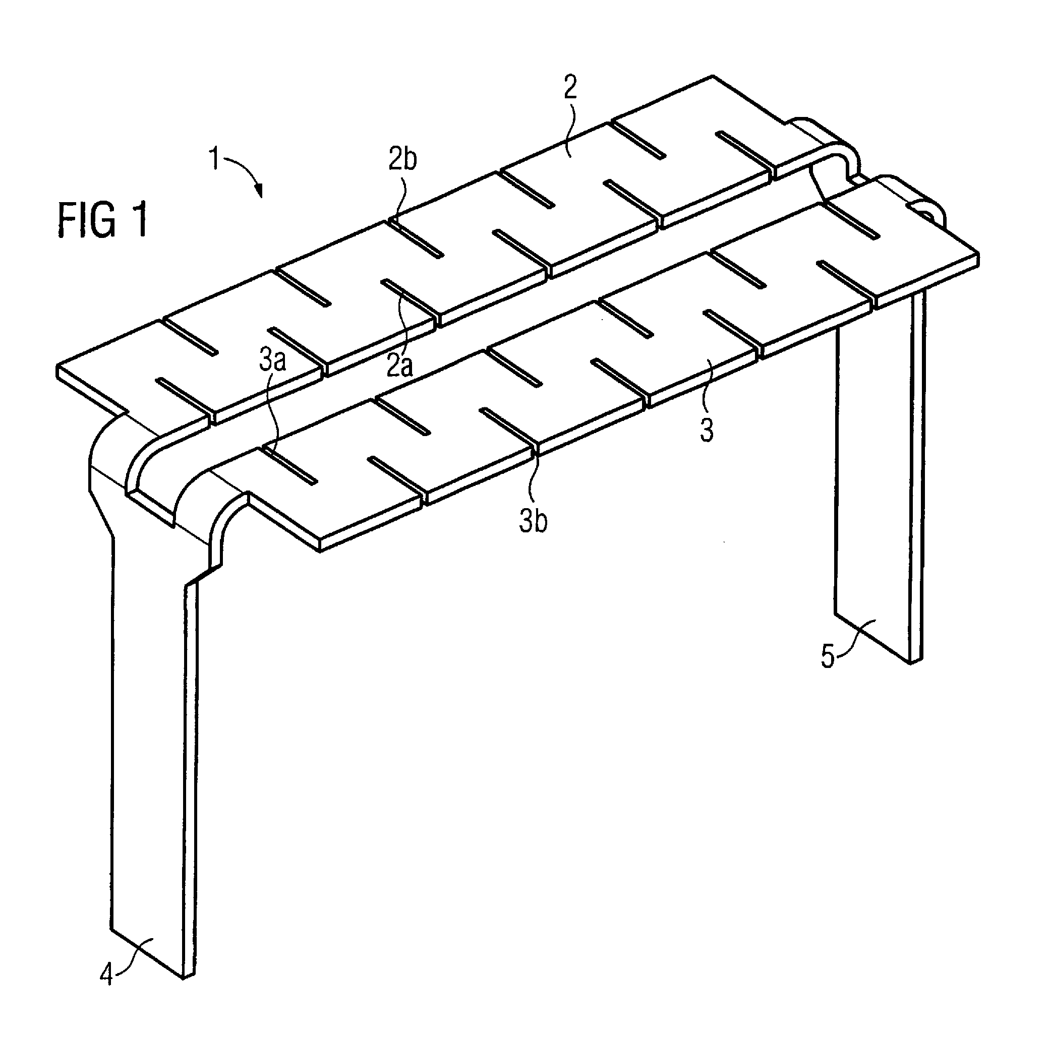
[0023]A parallel surface emitter that has two emitter surfaces 2 and 3 (partial emitters) separated from one another and possesses two small terminal legs or lugs 4 and 5 at its ends is designated with 1 in FIG. 1. The emitter surfaces 2 and 3 are executed as rectangles and consist of, for example, a plate of tungsten 0.05 mm thick with a side length of 1.45 mm by 10 mm. The emitter surfaces 2 and 3 respectively have incisions 2a, 2b, 3a and 3b that are arranged in alternation from two opposite sides and transversal to the longitudinal direction.

[0024]The emitter surfaces 2 and 3 are fashioned as a common component so that the emitter surfaces 2 and 3 thus lie at the same potential and thermionically emit electrons upon application of a heating voltage at the small terminal legs 4 and 5.

[0025]The surface emitter 1 can be processed just as simply as known surface emitters in terms of production. For example, the structures of the emitter surfaces 2 and 3 can be cut from a plate and b...


PUM


Abstract

A cathode HAS a cathode head in which a surface emitter is arranged that emits electrons upon application of a heating voltage. The surface emitter is fashioned as a parallel surface emitter with at least two emitter surfaces spaced apart from one another, to which at least one electrically conductive cutoff electrode is fed that is galvanically separated from the parallel surface emitter. Such a cathode has a good cutoff capability.

Description

BACKGROUND OF THE INVENTION[0001]1. Field of the Invention[0002]The present invention concerns a cathode of the type having a cathode head in which a surface emitter is arranged that emits electrons upon application of a heating voltage thereto.[0003]2. Description of the Prior Art[0004]A cathode of the above type in which the surface emitter has a rectangular footprint is known from DE 27 27 907 C2, for example. A surface emitter with a circular footprint is described in DE 199 14 739 C1. In the known surface emitters, a heating voltage is applied to the surface emitter during the operation of the x-ray tube, whereby electrons are emitted that are accelerated in the direction of an anode. X-ray radiation is generated in the surface of the anode upon impact of the electrons at the anode.[0005]Such a surface emitter has a distinctly larger radiant surface usable for emission relative to the volume to be heated and in comparison to a filament emitter. The surface emitter therefore can...

Claims


Application Information

Patent Timeline
Patent Type & Authority Patents(United States)
IPC IPC(8): H01J1/15
CPCH01J1/16H01J35/06H01J35/14H01J2235/06H01J35/064H01J35/066H01J35/147
Inventor FREUDENBERGER, JOERGKUTSCHERA, WOLFGANGROEHRICH, GUNTERSOELDNER, KARIN
Owner SIEMENS HEALTHCARE GMBH
Why Eureka
Try Eureka