Linear guide mechanism of lens barrel

a lens barrel and linear guide technology, applied in the direction of mountings, instruments, camera body details, etc., can solve the problems of restricting the miniaturization of the lens barrel, and the inability of linearly movable members to have a wide range of movement in the optical axis direction

Active Publication Date: 2012-10-23
HOYA CORP
View PDF18 Cites 0 Cited by
  • Summary
  • Abstract
  • Description
  • Claims
  • Application Information

AI Technical Summary

Benefits of technology

[0006]The present invention has been devised in view of the above described problems and provides a linear guide mechanism of a lens barrel which makes it possible to allow a wide range of movement of the linearly movable member, in the optical axis direction, while achieving miniaturization in size of the linear guide member in the optical axis direction.
[0011]In this manner, by making a single linear guide member undertake the linear guidance of the linearly movable member in the optical axis direction in a ready-to-photograph state (over the entire zooming range) at all times, the optical element can be guided in the optical axis direction with high precision.
[0020]According to the present invention, since it is possible to give the linearly movable member a range of movement in the optical axis direction which is greater than the length of each partial linear guide member in the optical axis direction, a lens barrel capable of giving the linearly movable member a wide range of movement in the optical axis direction while achieving a reduction in size of the linear guide member in the optical axis direction is achieved.

Problems solved by technology

For instance, in a zoom lens, if it is attempted to increase the range of movement of each movable lens group in the optical axis direction to achieve a high zoom ratio, the linear guide member for this movable lens group increases in size in the optical axis direction, thus restricting the miniaturization of the lens barrel, especially in the optical axis direction.
Conversely, if the linear guide member is small (short) in the optical axis direction, the linearly movable member cannot be made to have a wide range of movement in the optical axis direction.

Method used


Image

  • Linear guide mechanism of lens barrel
  • Linear guide mechanism of lens barrel
  • Linear guide mechanism of lens barrel

Examples


Embodiment Construction

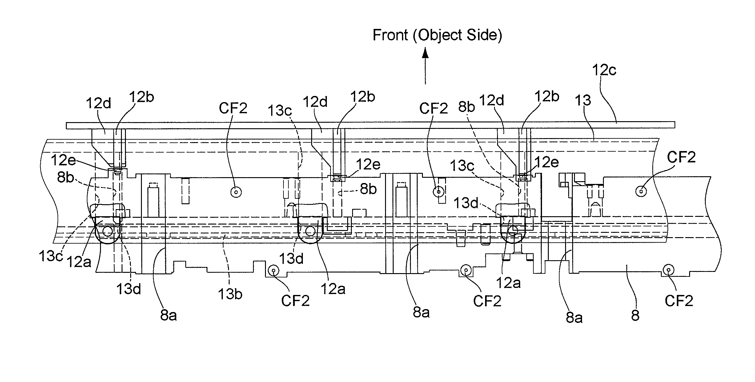
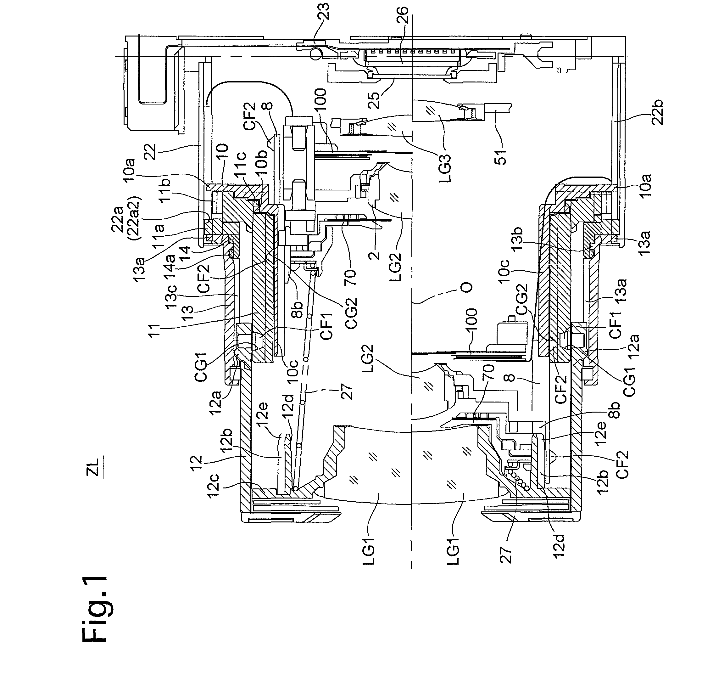
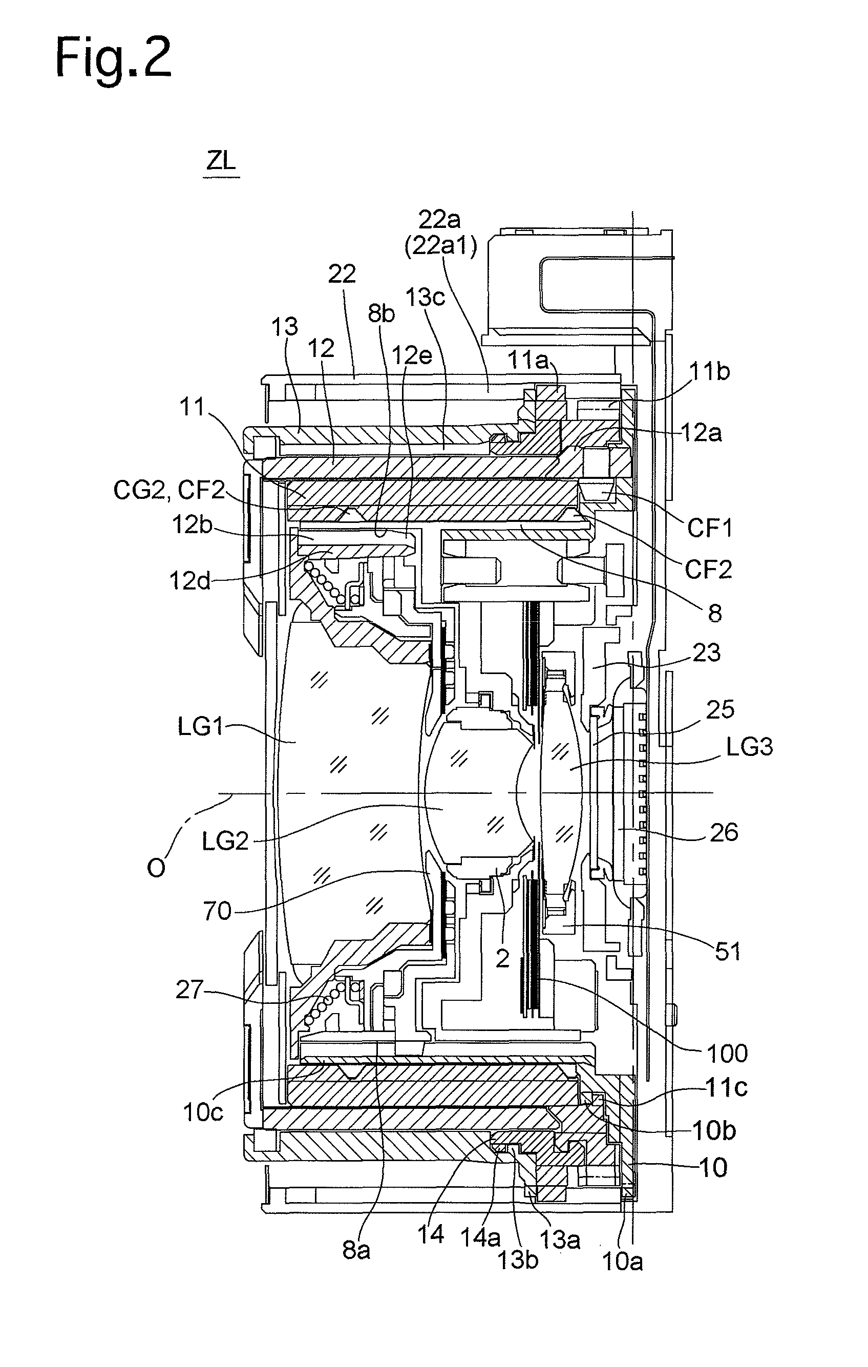
[0039]FIGS. 1 and 2 show an embodiment of a zoom lens barrel (zoom lens) ZL having a linear guide mechanism according to the present invention. A photographing optical system installed in the zoom lens barrel ZL is provided with a first lens group (optical element) LG1, a second lens group (optical element) LG2, a third lens group (focusing lens group) LG3, a low-pass filter (optical filter) 25 and an image sensor (image pickup device) 26, in that order from the object side. In the following descriptions, the optical axis direction refers to a direction along or parallel to an optical axis O of this photographing optical system, the front and the rear / behind refer to the object side and the image side, respectively; and the forward and rearward directions refer to the forward and rearward directions in the optical axis direction, respectively.

[0040]The low-pass filter 25 and the image sensor 26 are integrated as a single unit that is fixed to an image sensor holder 23, and the image...


PUM


Abstract

A linear guide mechanism of a lens barrel, the lens barrel including a rotatable ring, and a linearly movable member which holds an optical element and moves linearly in an optical axis direction by rotation of the rotatable ring, the linear guide mechanism includes a plurality of partial linear guide members which linearly guide the linearly movable member in the optical axis direction. A movement range of the linearly movable member in the optical axis direction is shared by a plurality of different movement ranges, via which the linearly movable member is linearly guided in the optical axis direction by the plurality of partial linear guide members, respectively.

Description

BACKGROUND OF THE INVENTION[0001]1. Field of the Invention[0002]The present invention relates to a linear guide mechanism of a lens barrel.[0003]2. Description of the Related Art[0004]In lens barrels such as those for cameras, it is often the case that an optical element holding member which holds an optical element such as a lens group is moved in an optical axis direction by a combination of a linear guide mechanism for guiding the optical element holding member linearly in the optical axis direction and a rotatable ring such as a cam ring. An example of such a lens barrel is disclosed in Japanese Unexamined Patent Publication 2004-151710.[0005]A typical linear guide mechanism of a lens barrel is structured by providing a linear guide member (such as a linear guide ring) with a set of guiding portions such as elongated grooves or guide keys, each of which includes a guide surface extending in an optical axis direction, and by providing a linearly movable member (such as a linearly...

Claims


Application Information

Patent Timeline
Patent Type & Authority Patents(United States)
IPC IPC(8): G02B15/14
CPCG02B7/10G03B17/04
Inventor NOMURA, HIROSHI
Owner HOYA CORP
Why Eureka
Try Eureka