
System And Method For Inserting Or Removing Cutting Inserts Of A Cutting Tool

a technology of cutting tools and cutting inserts, which is applied in the field of system and method for inserting or removing cutting inserts from tools, can solve the problems of inability to automate the replacement of cutting tools, wear and tear of cutting inserts during machining, and need to be replaced regularly

Pending Publication Date: 2022-06-02
PREMIUM AEROTEC
View PDF3 Cites 0 Cited by
  • Summary
  • Abstract
  • Description
  • Claims
  • Application Information

AI Technical Summary

Benefits of technology

The invention provides an automated system for replacing cutting inserts of cutting tools. The system includes a controller and two processing devices that work together to hold and align cutting inserts for easy removal and replacement. The first processing device holds the cutting insert in place while the second processing device secures it. This ensures that the cutting insert is always correctly aligned and reduces the risk of damage during removal. The system also includes a storage device with a centering device that holds the cutting insert in a specific position, making it easier to insert and align in the cutting tool. The first processing device can be a multi-axis robot that is flexible and adaptable to different machine tools and cutting tools. The holding mechanism can include a vacuum or clamping to secure the cutting insert. Overall, the system provides a more efficient and precise way to replace cutting inserts, especially in environments with a large number of machine tools.

Problems solved by technology

Such cutting inserts wear during machining and need to be replaced regularly.
Such a process is time-consuming and, in the case of larger cutting tools, cannot be carried out manually in an ergonomic manner Automated handling of cutting tools for replacement is hardly feasible in practice, as cutting inserts are sensitive to breakage due to their hardness and are difficult to align and fasten without canting due to their often small size.

Method used


Image

  • System And Method For Inserting Or Removing Cutting Inserts Of A Cutting Tool
  • System And Method For Inserting Or Removing Cutting Inserts Of A Cutting Tool
  • System And Method For Inserting Or Removing Cutting Inserts Of A Cutting Tool

Examples


Embodiment Construction

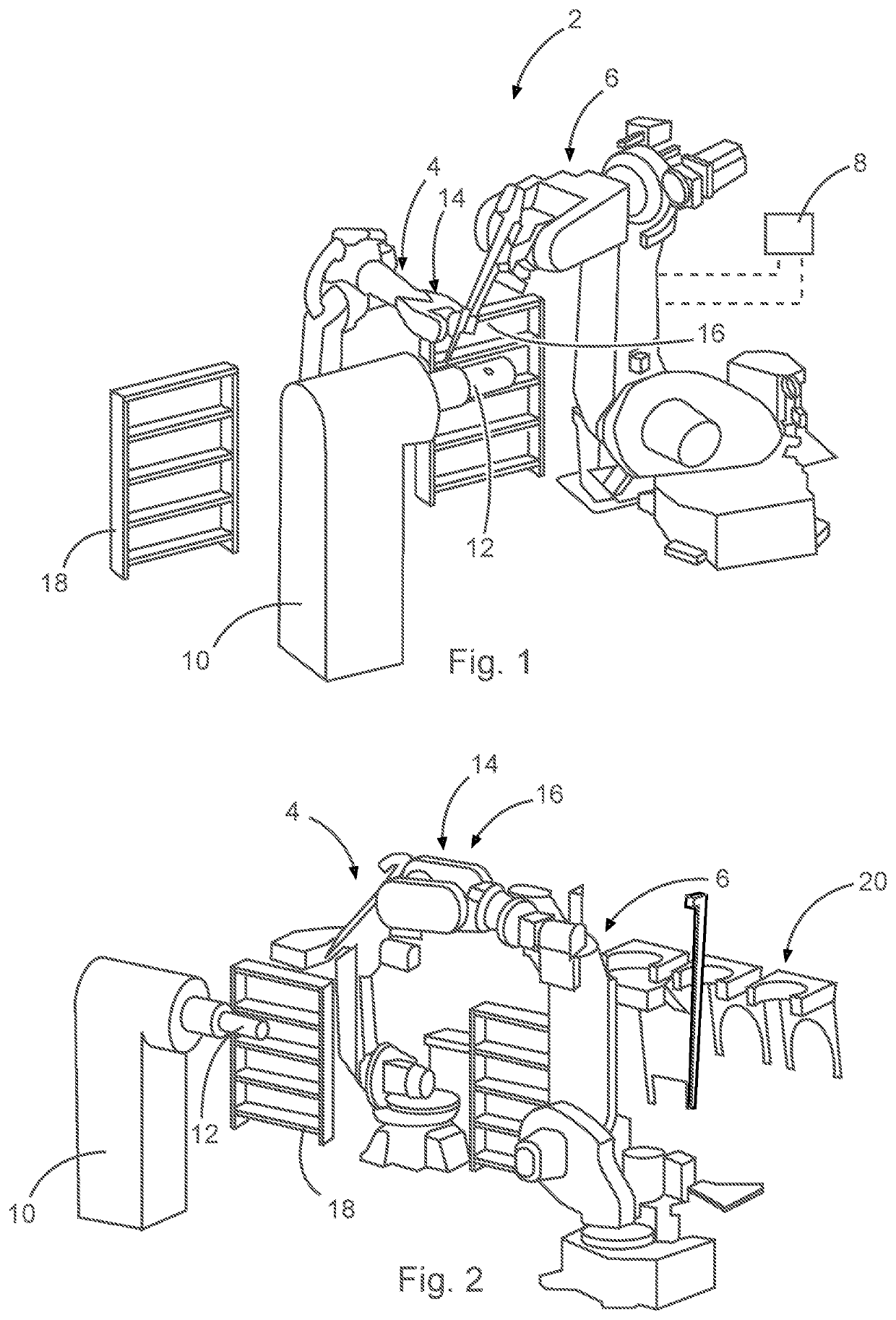
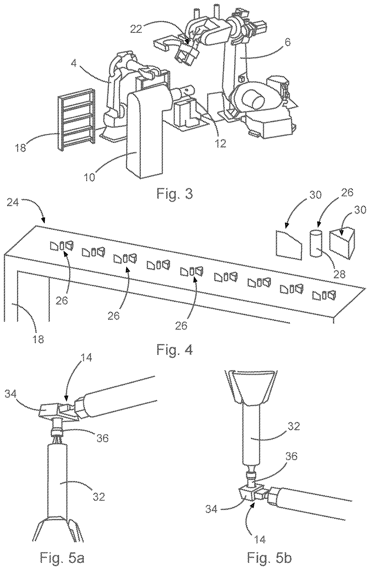
[0035]FIG. 1 shows a system 2 for inserting and removing cutting inserts of a cutting tool. The system 2 comprises a first processing device 4 and a second processing device 6. The processing devices 4 and 6 are implemented as multi-axis robots and are coupled to a controller 8, which may be implemented as a microcontroller, computer, or the like. The controller 8 may also be integrated in the respective processing device 4 or 6 itself instead of in the form of a separate device. Furthermore, FIG. 1 shows a fixing device 10 in which a cutting tool 12, which can hold one or more cutting inserts, can be fixed, and aligned. By arranging the cutting tool 12 on the fixing device 10, it is possible to handle the cutting insert separately from a machine tool. The fixing device 10 is adapted to selectively align the cutting tool 12 so that cutting inserts can be attached thereto or removed therefrom.

[0036]The first processing device 4 has a gripping element 14 for holding or securing a cutt...


PUM


Abstract

A system for inserting and removing cutting inserts of a cutting tool includes a first processing device, a second processing device, and a controller coupled to the first processing device and the second processing device, wherein the first processing device includes a gripping element for holding or securing a cutting insert, wherein the second processing device includes a fastening tool for fastening or releasing a fastening mechanism holding the cutting insert, and wherein the control is adapted to control the first processing device to hold the cutting insert, to control the second processing device to fasten or release the fastening mechanism when the cutting insert is held.

Description

FIELD OF THE INVENTION[0001]The invention relates to a system and method for inserting or removing cutting inserts from tools.BACKGROUND OF THE INVENTION[0002]Tools for machining workpieces often have replaceable cutting inserts. These are attached to a cutting tool and form cutting edges there. The cutting tool can be rigidly attached to a machine tool, for example in the form of a turning tool, or movable, in particular rotatable, for example as a milling head. Such cutting inserts wear during machining and need to be replaced regularly. Depending on the size of the cutting tool and a cycle of the machine tool, it may be necessary to remove the cutting tool from the machine tool for this purpose and then replace one or more cutting inserts arranged thereon. During the replacement, the machine tool could receive another cutting tool and continue machining in the meantime.[0003]When inspecting cutting inserts, a cutting insert is checked for wear. If necessary, this is then removed ...

Claims


Application Information

Patent Timeline
Patent Type & Authority Applications(United States)
IPC IPC(8): B25J11/00B25J15/06
CPCB25J11/005B25J15/0608B25J15/0616B23P19/04B23P19/06B25J9/0084B25J9/1682B25J15/0019B23P19/006B23Q3/15536B23Q2003/155404
Inventor KIEFER, LUCASMAEUSLE, CHRISTIAN
Owner PREMIUM AEROTEC
Learn More