Apparatus and method for controlling excitation frequency of magnetostrictive ultrasonic device

a technology of ultrasonic transducers and ultrasonic devices, which is applied in the field of ultrasonic transducers, can solve the problems of incompatible controllers, inductors, transformers, amplifiers, idemoto's controllers, etc., and achieves simple and inexpensive circuitry and components, simple and inexpensive components, and the effect of maximizing the power transferred to the working inser

Inactive Publication Date: 2012-10-23
EDEL ALAN +2
View PDF4 Cites 32 Cited by
  • Summary
  • Abstract
  • Description
  • Claims
  • Application Information

AI Technical Summary

Benefits of technology

[0017]It is an objective of the present invention that the frequency be set at an optimal value in a fully automatic manner that does not require any manual adjustment or settings by the practitioner. It is also an objective of the present invention that the frequency be automatically set at an optimal value for a variety of different handpieces and inserts, similarly without requiring any data to be entered by the practitioner.
[0019]It is furthermore an objective of the present invention that the above operating characteristics be attained through relatively simple and inexpensive circuitry and components, preferably utilizing integrated circuitry to the greatest extent possible, and reducing the need for reactive components, such as coils and capacitors. In keeping with this, it is an objective of the present invention that multiple handpieces, optionally containing inserts of different resonant frequencies, be accommodated without the need for additional complex circuitry.
[0020]The primary principle of the control apparatus and the method of operation according to the present invention is to control the frequency of the drive signal to the handpiece so as to maximize the power transferred to the working insert. The frequency corresponding to such maximum power transfer is typically at or near a resonance frequency of the coil-tip assembly and will therefore be referred to herein as resonance frequency, even though resonance (however defined) is not a necessary condition and is not detected as such when controlling the drive frequency. Rather a certain function of the current through the excitation coil is monitored, extracting certain measures therefrom and comparing these measures with corresponding optimal values that correspond to conditions of maximum power transfer. Such optimal values are obtained during infrequent calibration runs, performed on combinations of each type of handpiece and insert to be used—preferably in a laboratory or in the factory, where accurate mechanical- and / or electrical power measuring equipment is available. The advantage of the principle employed in the present invention, as outlined above and as further explained below, is that it obviates the need to include in the controller elaborate circuits and components for directly measuring the power transferred to the magnetostrictive insert—accurately and continuously—replacing them by relatively simple and inexpensive components.

Problems solved by technology

Instead, Sakurai relies on a rather complex arrangement of inductors, transformers, and amplifiers to detect and match the impedance of the transformer.
The handpiece disclosed in Sakurai has no excitation coil; moreover, the controller disclosed in Sakurai is not compatible with magnetostrictive inserts.
As with Sakurai, Idemoto's handpiece lacks an excitation coil; the transducer disclosed in Idemoto is not of the magnetostrictive variety; moreover, Idemoto's controller is incompatible with magnetostrictive inserts.
Furthermore, the oscillator of Sharp '161 has a limited range of operation, and normally can accommodate only inserts having a restricted range of resonant frequencies.
The transformer feedback of Sharp '161 is not suitable for such an arrangement.
Furthermore, Gofman still requires several coils in addition to the excitation coil, thereby incurring additional circuitry complexity and bulk.
Although Feine thus suggests a means of reaching the resonant frequency, the requirement for additional power-measurement circuitry imposes further requirements and limitations.
This, again, does not ensure peak power transfer.
Ureche advocates operating at a frequency intermediate between series resonance and parallel resonance, attempting to minimize the reactive component of the admittance; he does not, however, teach how to achieve this in a practical and efficient manner, nor does he prove that this would result in maximum power transfer.
The disadvantage of Williams' controller lies in the elaborate, and thus expensive, arrangement for continuously measuring the power.

Method used


Image

  • Apparatus and method for controlling excitation frequency of magnetostrictive ultrasonic device
  • Apparatus and method for controlling excitation frequency of magnetostrictive ultrasonic device
  • Apparatus and method for controlling excitation frequency of magnetostrictive ultrasonic device

Examples


Embodiment Construction

[0039]The principles and operation of a controller for magnetostrictive ultrasonic dental devices according to the present invention may be understood with reference to the drawings and the accompanying description.

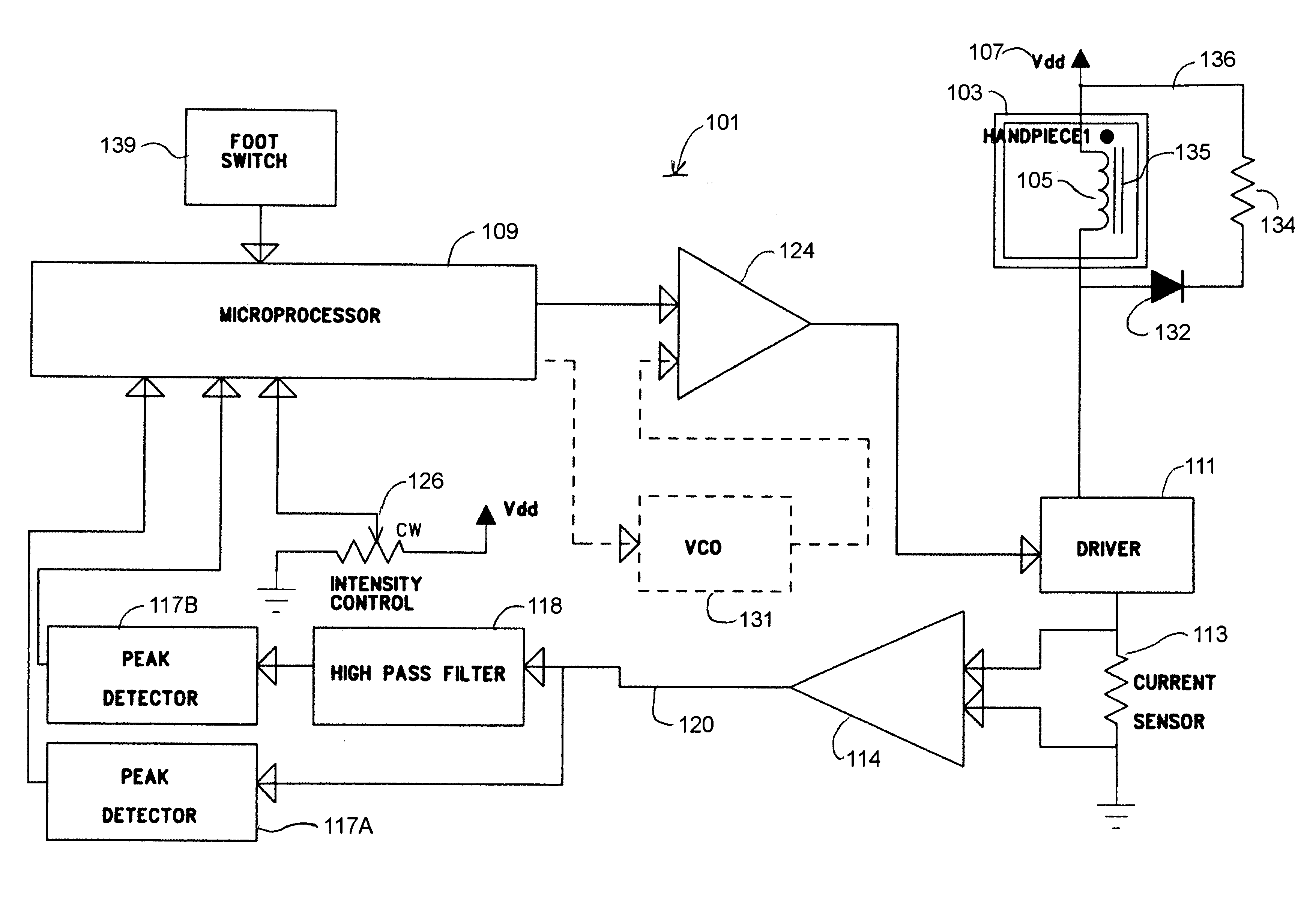
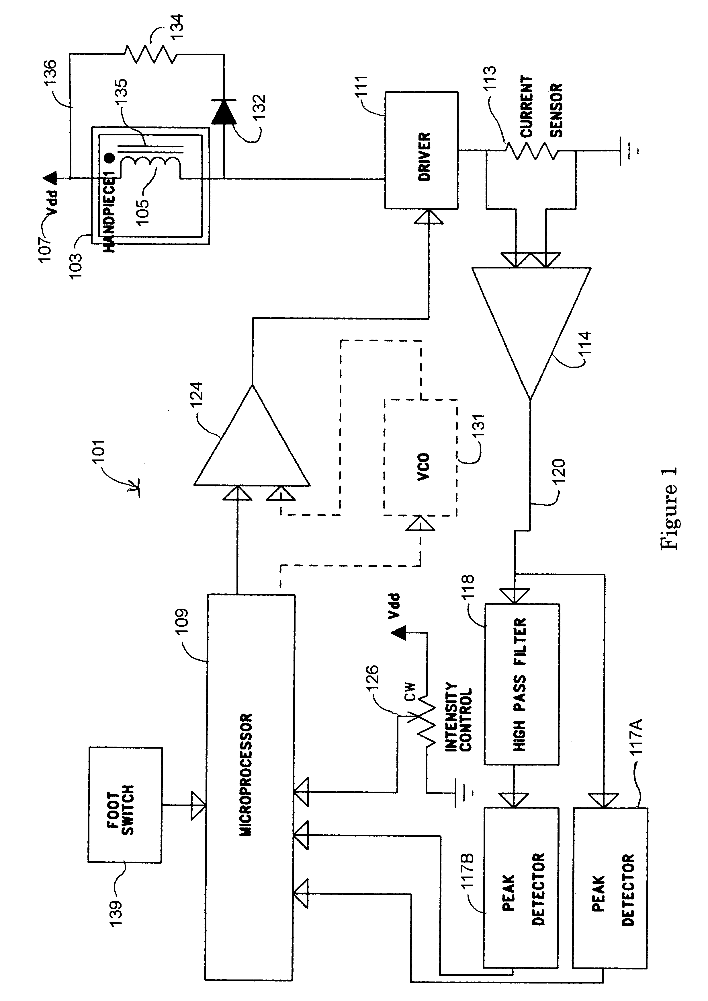
[0040]FIG. 1 is a conceptual block diagram of a magnetostrictive dental scaler system according to an embodiment of the present invention. A controller 101 controls the current through an excitation coil 105 in a separate handpiece 103. A magnetostrictive insert 135 is placed within handpiece 103 within excitation coil 105. (Insert 135 is shown schematically in FIG. 1. In practice, insert 135 is placed physically within the confines of excitation coil 105, such that the tip of insert 135 is exposed and available for cleaning the surfaces of the patient's teeth).

[0041]Coil 105 is connected, in series with a driver 111 and a current sensor 113, between a voltage source 107, and the other end of coil 105 connects to a return path (e.g. ground) 108. Driver 111 is generally co...


PUM


Abstract

Apparatus and method for controlling the frequency of the current in the excitation coil of a handpiece of a dental magnetostrictive ultrasonic scaling unit, or a similar transducer. A microprocessor continually samples predetermined functions of the current through the excitation coil, and periodically adjusts the frequency, by performing a coarse-stepped frequency scan, followed by a fine-stepped frequency scan until the function samples are close to predetermined optimum values. The functions can include the peak of the current and the peak of a high-pass filtered version of the current. The frequency adjustment is performed each time the handpiece is energized by the practitioner, and at frequent intervals thereafter, assuring automatic optimal frequency at all times and under all conditions. Apparatus according to the invention does not require sensing coils or complex power- or impedance-sensing circuitry and covers a wide range of resonant frequencies for different handpiece- and insert types. A configuration with multiple handpieces is supported.

Description

[0001]The present application is continuation-in-part of U.S. patent application Ser. No. 11 / 351,436, filed on Feb. 13, 2006 now U.S. Pat. No. 7,715,167 and published on Aug. 24, 2006 as Pub. No. US2006 / 0188841; it claims benefit of U.S. Provisional Patent Application No. 60 / 655,103 filed Feb. 23, 2005.FIELD OF THE INVENTION[0002]The present invention relates to controllers for ultrasonic transducers and, more particularly, to the control of the excitation frequency of a magnetostrictive ultrasonic transducer for dental use.BACKGROUND OF THE INVENTION[0003]The use of a magnetostrictive transducer for an ultrasonic dental device, such as a dental scaler, is well-known and standardized throughout the dental profession. Such devices are characterized by having a handpiece into which a removable insert with a working tip is placed. The handpiece contains an excitation coil which is electrically connected via a cable to a control unit, or controller, that provides the excitation energy t...

Claims


Application Information

Patent Timeline
Patent Type & Authority Patents(United States)
IPC IPC(8): H01H47/00A61C1/07
CPCA61C17/20A61C3/03
Inventor EDEL, ALANEDEL, JULIANCHAVKIN, SIMEON
Owner EDEL ALAN
Why Eureka
Try Eureka