Bridgeless power factor correction circuit with improved critical mode (CRM) operation

a technology of critical mode and power factor, applied in the field of bridgeless power factor correction circuits, can solve the problems of heat generation and power loss in resistors becoming impediments, circuit constitution and control becomes complicated, etc., and achieves the effect of simple circuit and low cos

Inactive Publication Date: 2015-07-14
MINEBEAMITSUMI INC
View PDF13 Cites 2 Cited by
  • Summary
  • Abstract
  • Description
  • Claims
  • Application Information

AI Technical Summary

Benefits of technology

[0008]The present invention has been made in view of the above-described problems, and an object of the invention is to provide a power factor correction circuit wherein the point in time at which the reactor current becomes zero can be detected with an inexpensive and simple circuit constitution.
[0014]Since the power factor correction circuit of the present invention is constructed as described hereinabove, in a bridgeless power factor correction circuit, it makes possible to detect a point where a reactor current becomes zero based on low-cost and simplified circuit structures.

Problems solved by technology

However, for example, in a current detection technology using a current transformer, there has been a problem in that an additional circuit such as a reset circuit is generally necessary in order to achieve the necessary detection accuracy, and thus the circuit constitution and the control thereof becomes complicated.
However, in this case, heat generation and power loss in the resistor may become an impediment to miniaturization and efficiency improvement of the power factor correction circuit, and by extension the power supply apparatus itself.

Method used


Image

  • Bridgeless power factor correction circuit with improved critical mode (CRM) operation
  • Bridgeless power factor correction circuit with improved critical mode (CRM) operation
  • Bridgeless power factor correction circuit with improved critical mode (CRM) operation

Examples


first embodiment

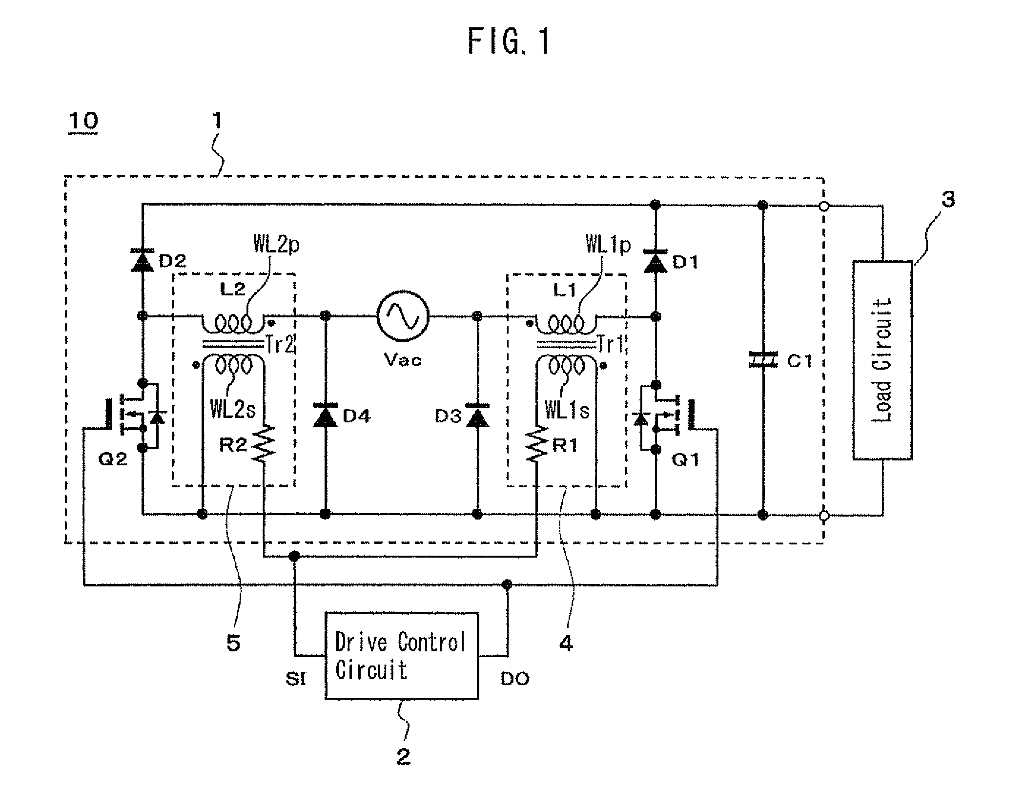
[0026]Hereinafter, embodiments of the present invention will be described with reference to the attached drawings. FIG. 1 is a circuit constitution diagram illustrating a power supply apparatus 10 including a power factor correction circuit 1 according to the present invention. In the power supply apparatus 10, the power factor correction circuit 1 functions to rectify, boost, and correct the power factor of an AC voltage of an AC power source Vac, and then apply it to a load circuit 3. Therein, the load circuit 3 is typically constituted by a DC-DC converter circuit or a DC-AC converter circuit, and the power factor correction circuit 1 constitutes an input stage of the power supply apparatus 10 that on the whole forms an AC-DC converter or an AC-AC converter. However, the present invention is not limited by the specific constitution of the load circuit 3, and any appropriate circuit can be used.

[0027]The power factor correction circuit 1 includes the first series circuit consistin...

second embodiment

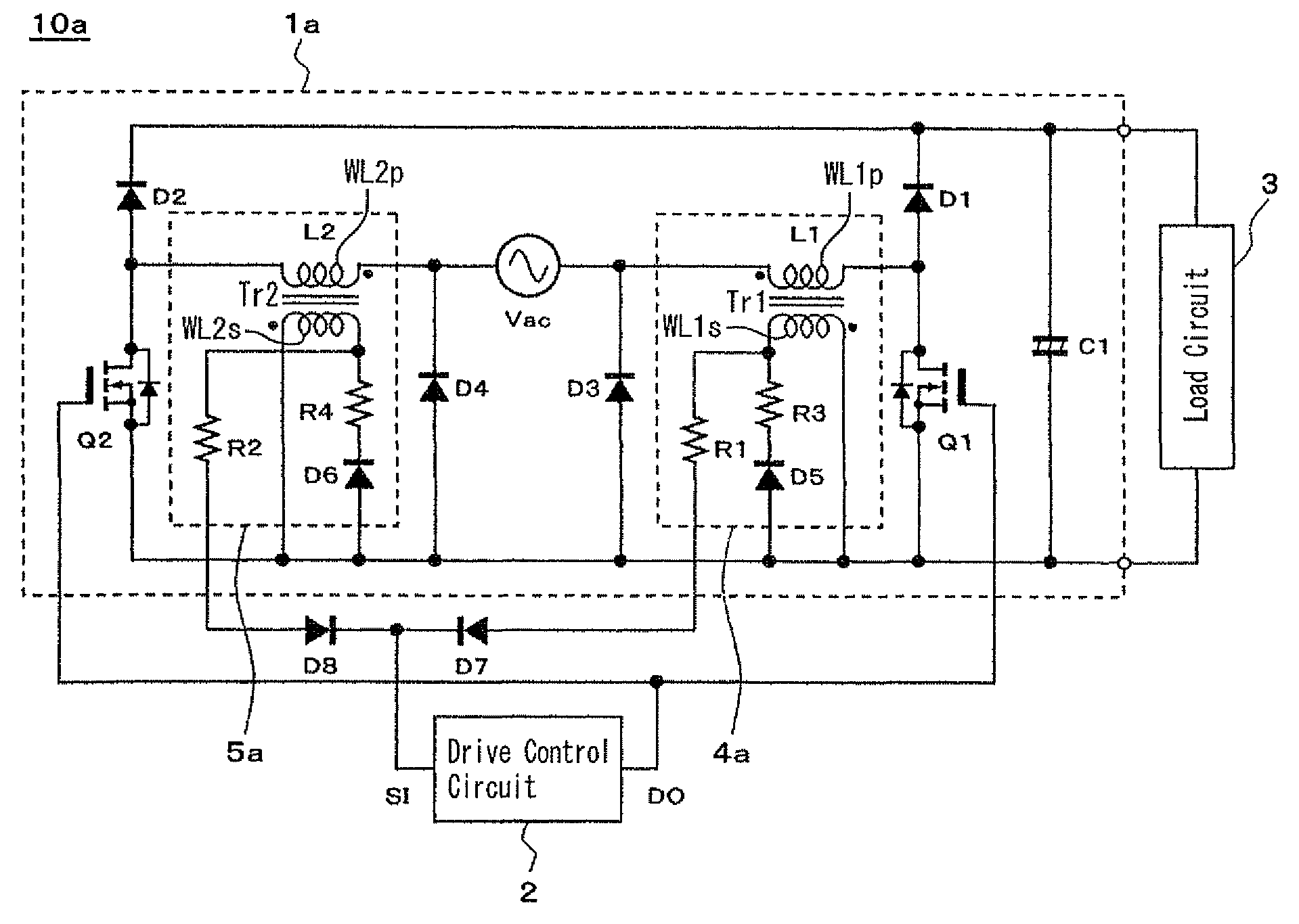
[0056]FIG. 3 is a circuit constitution diagram illustrating a power supply apparatus 10a including a power factor correction circuit 1a according to the present invention. The power factor correction circuit 1a differs from the power factor correction circuit 1 illustrated in FIG. 1 with respect to the following points. In the power factor correction circuit 1a, one end of a resistor R3 is connected to the connecting point of the secondary winding WL1s of the first transformer Tr1 and the resistor R1, the cathode terminal of the fifth rectifier element (diode) D5 is connected to the other end of the resistor R3, and the anode terminal of the fifth rectifier element D5 is connected to the common line. Similarly, one end of a resistor R4 is connected to the connecting point of the secondary winding WL2s of the second transformer Tr2 and the resistor R2, the cathode terminal of the sixth rectifier element (diode) is connected to the other end of the resistor R4, and the anode terminal ...

third embodiment

[0060]FIG. 4 is a circuit constitution diagram illustrating a power supply apparatus 10b including a power factor correction circuit 1b according to the present invention. The power factor correction circuit 1b differs from the power factor correction circuit 1 illustrated in FIG. 1 with respect to the following points. In the power factor correction circuit 1b, the secondary winding WL1s of the first transformer Tr1 and the resistor R1 are connected via a ninth rectifier element (diode) D9, the anode terminal of the ninth rectifier element D9 is connected to one end of the secondary winding WL1s, and the cathode terminal of the ninth rectifier element D9 is connected to one end of the resistor R1.

[0061]The cathode terminal of the ninth rectifier element D9 is connected to an emitter terminal of the third switching element Q3 consisting of a PNP transistor. The connecting point of the anode terminal of the ninth rectifier element D9 and the secondary winding WL1s is connected to a b...


PUM


Abstract

A power factor correction circuit includes: the first series circuit consisting of the first rectifier element and the first switching element; the second series circuit consisting of the second rectifier element and the second switching element; the first / second reactors; and the first / second current detectors. The first / second current detectors have each the first / second transformers, both primary parts of which consist of the first / second reactors. The first and the second switching elements are controllable based on the first output signal according to the reactor current from the secondary side of the first transformer and the second output signal according to the reactor current from the secondary side of the second transformer so as to apply a desired DC voltage to the load circuit.

Description

BACKGROUND OF THE INVENTION[0001]1. Field of the Invention[0002]The present invention relates to a power factor correction circuit, and particularly to operation in a critical mode of a bridgeless power factor correction circuit.[0003]2. Description of the Related Art[0004]Conventionally, in order to supply electric power to a load, a power source apparatus in which an AC (alternating current) voltage from an input AC power source is rectified and then converted to a desired AC or DC (direct current) voltage and supplied to the load has been widely used. In this kind of power source apparatus, a power factor correction circuit needs to be provided in order to correct the power factor and reduce the EMI noise generated by the apparatus. Therefore, in a general constitution of a power supply apparatus, a rectification circuit consisting of a diode bridge and a power factor correction circuit consisting of a boost converter circuit are utilized in the input stage.[0005]In recent years,...

Claims


Application Information

Patent Timeline
Patent Type & Authority Patents(United States)
IPC IPC(8): H02M1/42
CPCH02M1/4225Y02B70/126Y02B70/10Y02P80/10
Inventor NISHIBORI, KOHEICHALERMBOON, NADTHAWUT
Owner MINEBEAMITSUMI INC
Why Eureka
Try Eureka