Emcw layer thickness measurement apparatus and method

a technology of emcw and measurement apparatus, which is applied in the direction of measurement devices, instruments, and using reradiation, can solve the problems of inaccurateness and sometimes impaired validity of measurement, and achieve the effects of reducing the influence of imperfections such as non-linearity or temporal fluctuations of emcw frequency modulation, and simple and inexpensive circuitry

Inactive Publication Date: 2017-09-28
SYSMETRIC LTD
View PDF0 Cites 1 Cited by
  • Summary
  • Abstract
  • Description
  • Claims
  • Application Information

AI Technical Summary

Benefits of technology

[0012]According to some embodiments, dE, being an estimation of the distance D which is to be measured to the surface of the object, is roughly equal to D. Consequently, ΔT is roughly equal to the delay by which the received signal is delayed (relative to the transmitted signal, namely the first portion of the EMCW), hence the received signal and the delayed signal have roughly the same frequency. It is emphasized that if the time delay ΔT is equal exactly to delay by which the received signal is delayed, then the frequencies of the received signal and the delayed signal are identical, regardless of the time dependency of the frequency modulation of the EMCW. In other words, for any continuous frequency modulation (e.g. triangle, sinusoidal, saw-tooth (in the linear regime), etc.) the closer the time delays are, the closer are the frequencies of the delayed signal and the received signals; and when the time delays are equal, then the frequencies are equal. Thus, by equating, at least roughly, the time delay of the delayed signal with that of the received signal, influence of imperfections such as non-linearity or temporal fluctuations of the frequency modulation of the EMCW is reduced. Consequently, according to some embodiments, distance measurement with sub-wavelength accuracy may be achieved, using even frequency modulation that may deviate from perfect linearity, which requires in turn relatively simple and inexpensive circuitry.

Problems solved by technology

In such gauge measurements, the accuracy, and sometimes the validity of the measurement, may be impaired because the phase shift signal may include frequency components caused by reflections of the electromagnetic waves from surfaces other than the material being monitored (e.g. from the waveguide, from the sides of the tank, etc).

Method used


Image

  • Emcw layer thickness measurement apparatus and method
  • Emcw layer thickness measurement apparatus and method
  • Emcw layer thickness measurement apparatus and method

Examples


Embodiment Construction

[0029]The principles, uses and implementations of the teachings herein may be better understood with reference to the accompanying description and figures. Upon perusal of the description and figures present herein, one skilled in the art is able to implement the teachings herein without undue effort or experimentation. In the figures, like reference numerals refer to like parts throughout.

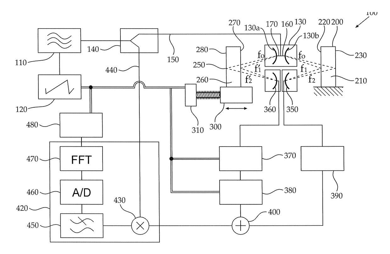
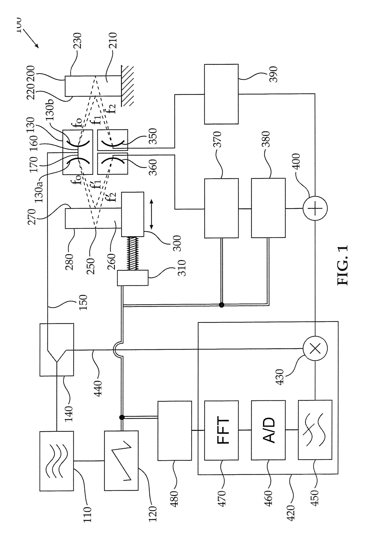
[0030]FIG. 1 schematically depicts an embodiment of an apparatus 100 for thickness measurements of layers, particularly (but not necessarily) of electrically isolating materials such as polymers, glass, ceramics and the like. The description herein relates to an illustrative example of a thickness measurement of a single layer; however a person skilled in the art may readily observe that the method may qualify and may be capable of providing thickness measurement of a desired layer in a multi-layer object, as is further explained below. The measurement described herein, according to some embodimen...


PUM


Abstract

A method is provided for measuring a distance to a surface of an object using an electromagnetic continuous wave (EMCW). The method comprises obtaining an estimation dE of the distance to the surface. The method further comprises generating an electromagnetic continuous wave (EMCW) having a frequency in the range between about 100 MHz and about 1 THz, wherein the EMCW is frequency modulated so that the frequency thereof is controllably varied and transmitting a measurement portion of the EMCW towards the surface of the object. The method further comprises receiving a received signal from a reflection of the transmitted EMCW from the surface of the object and generating a combined signal by combining the received signal with a delayed signal, the delayed signal being obtained by delaying a reference portion of the EMCW by a controllably variable time delay ΔT, ΔT being dictated by dE. The method further comprises measuring a parameter of the combined signal, thereby measuring the distance to the surface of the object.

Description

FIELD OF THE INVENTION[0001]The invention, in some embodiments, relates to the field of layer thickness measurements and more particularly, but not exclusively, to thickness measurements of layers of electrically isolating materials using frequency modulated, continuous electromagnetic waves.BACKGROUND OF THE INVENTION[0002]A layer thickness measurement may come important in many industrial applications, for instance in quality assurance and control of production lines. In production lines of items such as plates, sheets, pipes or coated products, parameters such as absolute layer thickness and variation of layer thickness (e.g. variations between different areas of the same item, or variations between items) are directly related to the absolute quantity of raw material used in the manufacturing process and to adequacy of the item characteristics (such as evenness, symmetry, strength etc.) to the item's required specifications.[0003]Several methods and technologies are currently kno...

Claims


Application Information

Patent Timeline
Patent Type & Authority Applications(United States)
IPC IPC(8): G01S13/32
CPCG01S13/32G01S13/08
Inventor GOZNI, GILIMAOZ, SHAIKE
Owner SYSMETRIC LTD
Why Eureka
Try Eureka