Power source apparatus

a power source and power supply technology, applied in the direction of electric variable regulation, process and machine control, instruments, etc., can solve the problems of increasing emi noise, complicated circuit structure and control thereof, etc., and achieves low cost, high efficiency, and reduced emi noise

Inactive Publication Date: 2015-04-07
MINEBEAMITSUMI INC
View PDF4 Cites 2 Cited by
  • Summary
  • Abstract
  • Description
  • Claims
  • Application Information

AI Technical Summary

Benefits of technology

[0009]The present invention has been made in view of the above-described problems, and an object of the present invention is to provide a power source apparatus including a power factor correction circuit that is highly efficient and capable of reducing EMI noise, in which the point in time at which the reactor current becomes zero can be detected with an inexpensive and simple circuit constitution.
[0016]The power factor correction circuit according to the present invention is constituted as described above, and thus a power source apparatus including a power factor correction circuit that is highly efficient and capable of reducing EMI noise, in which the point in time at which the reactor current becomes zero can be detected with an inexpensive and simple circuit constitution, can be provided.

Problems solved by technology

However, for example, in a current detection technology using a current transformer, there has been a problem in that an additional circuit such as a reset circuit is necessary in order to achieve the necessary detection accuracy, and thus the circuit constitution and the control thereof becomes complicated.
However, in the power factor correction circuit disclosed in JP-A No. 2011-152017, there has been a problem in that a side of the output terminal of the AC power source which is connected to the reactor enters a floating state relative to the ground of the power factor correction circuit, and this leads to an increase in the EMI noise.

Method used


Image

  • Power source apparatus
  • Power source apparatus
  • Power source apparatus

Examples


first embodiment

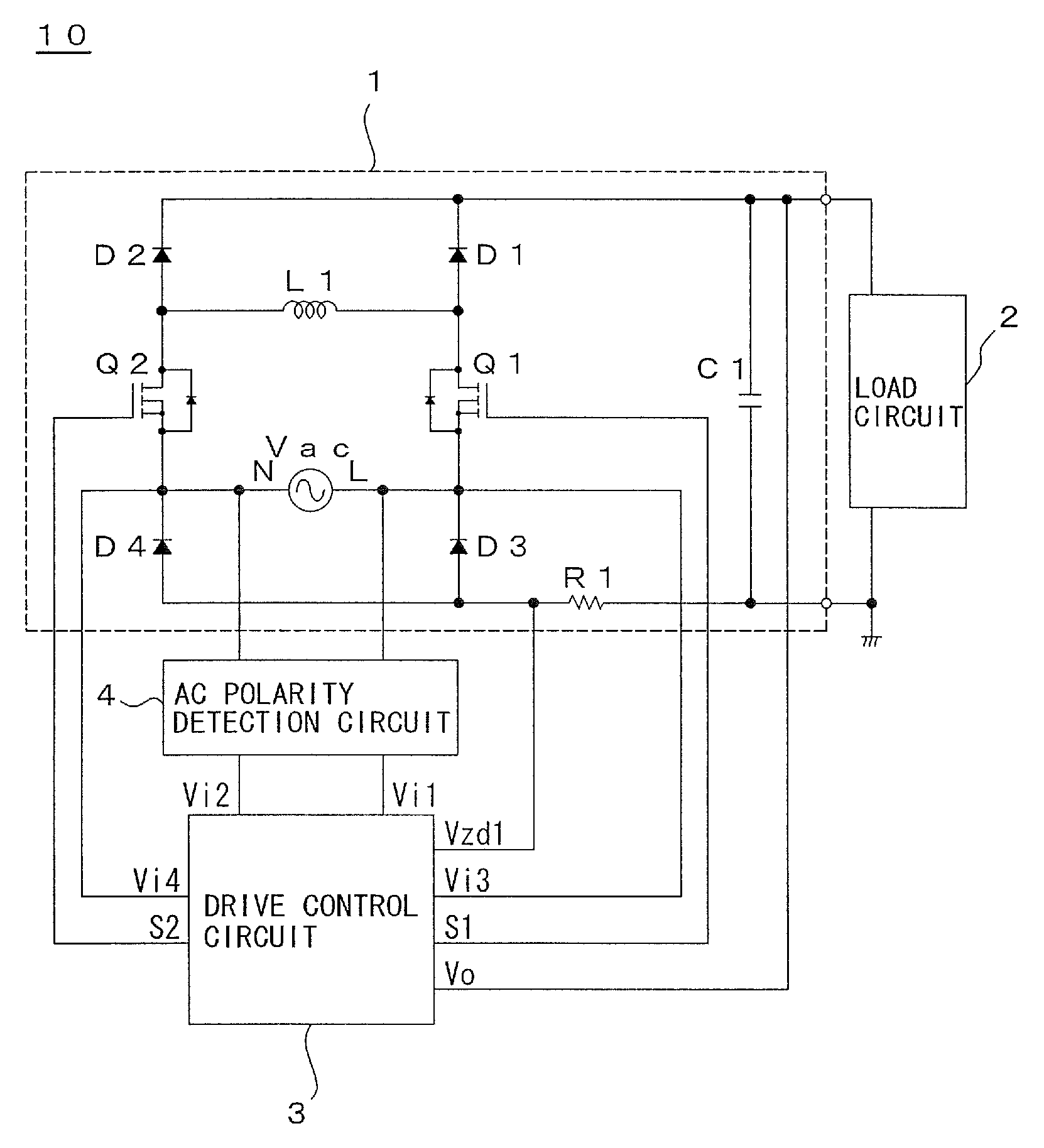
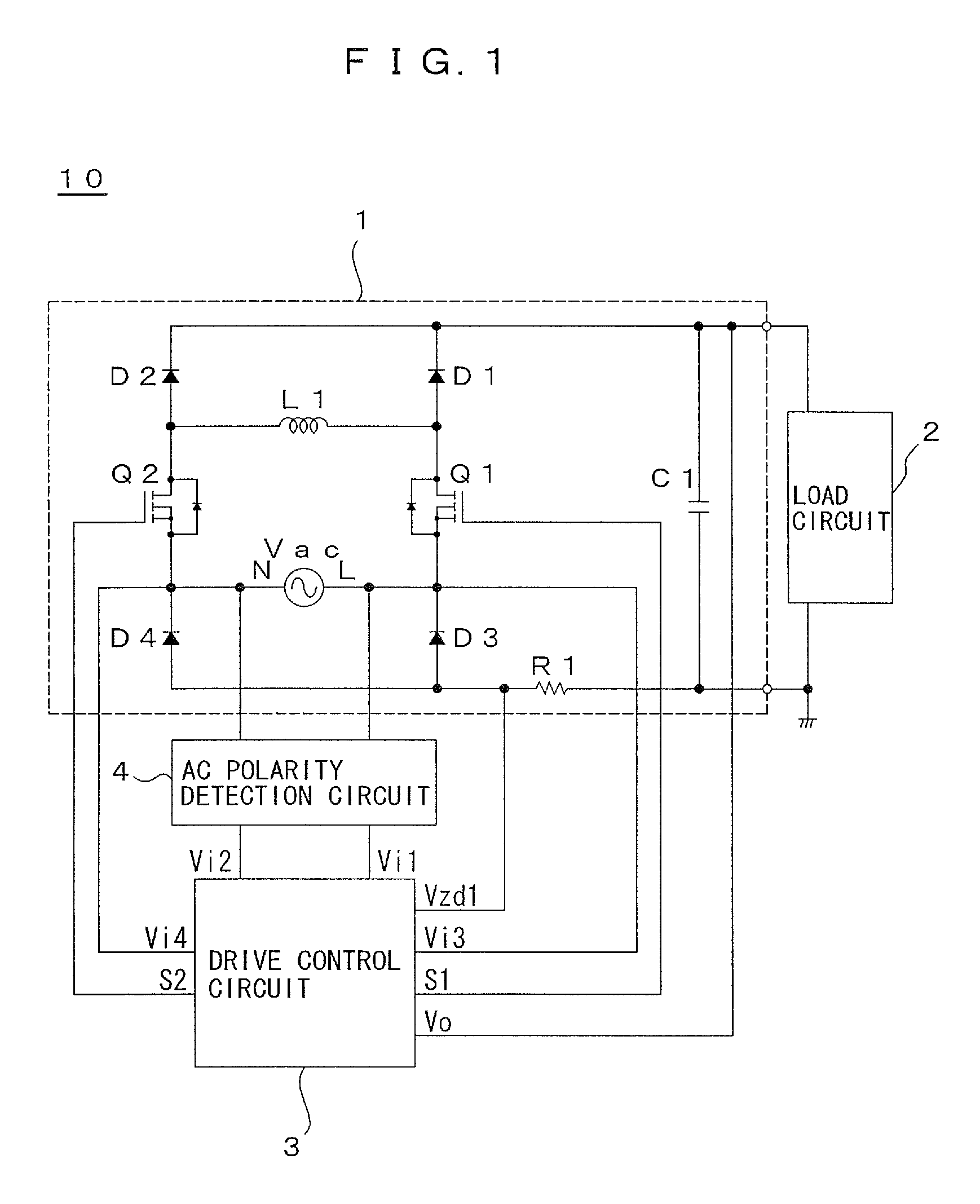
[0025]FIG. 1 is a circuit constitution diagram illustrating a power source apparatus 10 according to the present invention.

[0026]The power source apparatus 10 has a power factor correction circuit 1. The power factor correction circuit 1 functions to rectify, boost, and correct the AC voltage of an AC power source Vac. The voltage that has been subjected to the rectification, the boost, and the correction then applies to a load circuit 2. The load circuit 2 is typically constituted by a DC-DC converter circuit or a DC-AC converter circuit, and the power factor correction circuit 1 constitutes an input stage of the power source apparatus 10 that on the whole forms an AC-DC converter or an AC-AC converter. However, the present invention is not limited by the specific constitution of the load circuit 2, and any appropriate circuit may be applied.

[0027]The power factor correction circuit 1 includes a first series circuit (indicated by reference numeral “D1-Q1-D3” when necessary) consist...


PUM


Abstract

A power source apparatus includes: a first series circuit that has a first rectifier element, a first switching element, and a third rectifier element; a second series circuit that has a second rectifier element, a second switching element, and a fourth rectifier element; a reactor connected between a connecting point of the first rectifier element and the first switching element and a connecting point of the second rectifier element and the second switching element; and a current detection unit having a first resistor element. The first and second switching elements are controllable based on a first zero current detection signal in accordance with a first current detected in the current detection unit, and a desired direct current voltage is fed to a load circuit.

Description

BACKGROUND OF THE INVENTION[0001]1. Field of the Invention[0002]The present invention relates to a power source apparatus having a power factor correction circuit function, and particularly to operation in a critical mode of a bridgeless power factor correction circuit of a power source apparatus.[0003]2. Description of the Related Art[0004]Conventionally, in order to supply electric power to a load, a power source apparatus in which an AC (alternating current) voltage from an input AC power source is rectified and then converted to a desired AC or DC (direct current) voltage and supplied to the load has been widely used. In this kind of power source apparatus, a power factor correction circuit needs to be provided in order to correct the power factor and reduce the EMT noise generated by the power source apparatus. Therefore, in a general constitution of a power source apparatus, a rectification circuit consisting of a diode bridge and a power factor correction circuit consisting o...

Claims


Application Information

Patent Timeline
Patent Type & Authority Patents(United States)
IPC IPC(8): H02M5/42H02M7/04H02M7/68G05F5/00H02M1/42
CPCH02M1/4208H02M1/4225Y02B70/126Y02B70/10Y02P80/10H02M1/0085
Inventor NISHIBORI, KOHEICHALERMBOON, NADTHAWUT
Owner MINEBEAMITSUMI INC
Why Eureka
Try Eureka