
Electromagnetic apparatus for measuring angular position

a technology of angular position and electric field, applied in the direction of resistance/reactance/impedence, devices using electric/magnetic means, instruments, etc., can solve the problems of phase delay or a change in resonant frequency, and achieve the effect of increasing sensitivity, increasing sensitivity, and increasing sensitivity

Inactive Publication Date: 2009-09-01
NYCE DAVID S +1
View PDF8 Cites 2 Cited by
  • Summary
  • Abstract
  • Description
  • Claims
  • Application Information

AI Technical Summary

Benefits of technology

[0011]The present invention employs at least two resonators formed by counter-wound radial spirals, electrodynamic parameters of the resonators being informative parameters of position, rotation velocity, and the like. These resonators are excited in the opposite-phase mode and are sensitive to a target having electrical conductivity in the direction of the windings. The main advantages of apparatus according to the present invention, in comparison to prior art, are: very large sensitivity to the rotation of the target and simplicity of converting the informative parameter into a position reading.
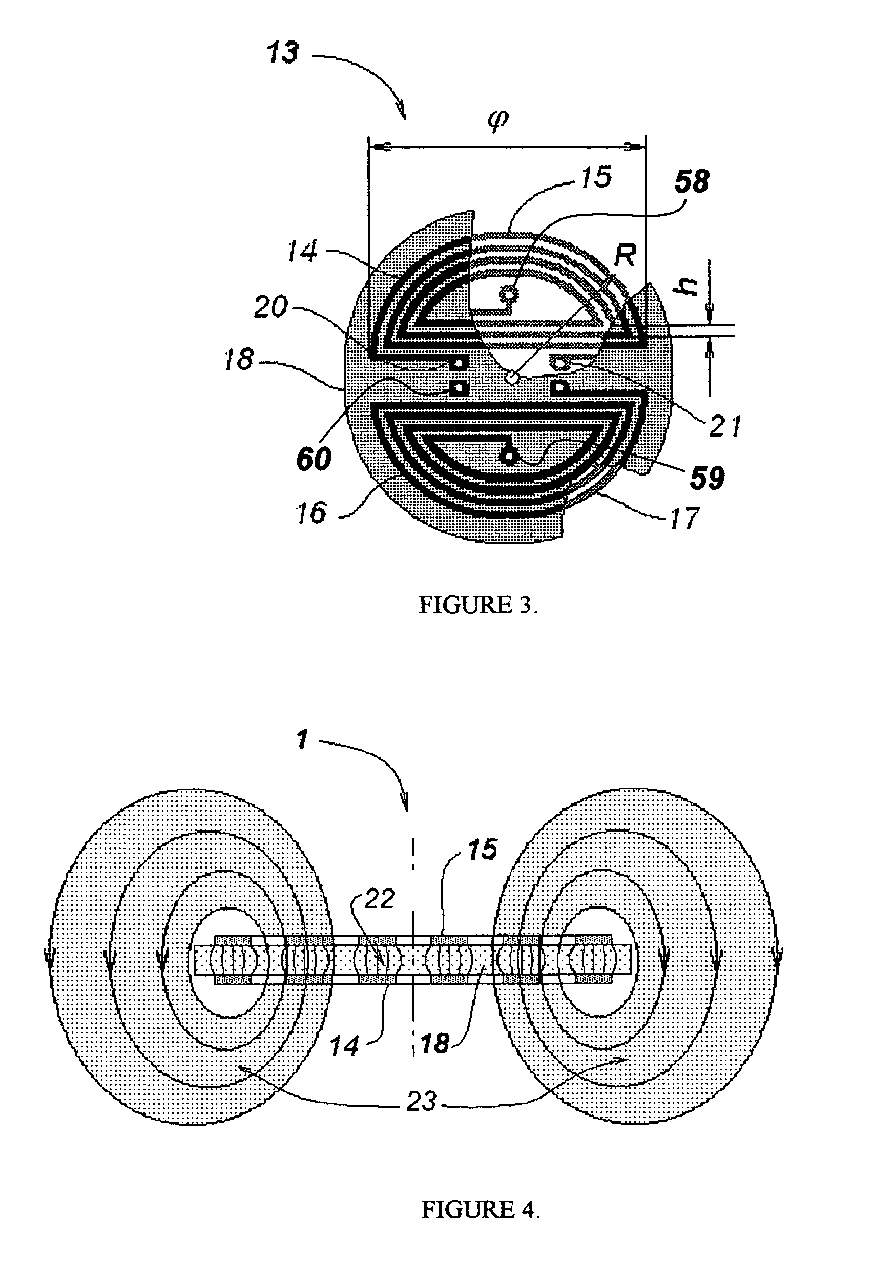
[0012]An increase in sensitivity is achieved due to the concentration of electromagnetic energy near the rotating surface, and due to splitting of the electric and magnetic fields: the electric field is concentrated between the conductors of the slow-wave structures that form each resonator, and the magnetic field is disposed in the region between the resonator and the target. An additional increase in sensitivity is caused by a comparison of the impedances of the resonators (a differential measurement). The direction of rotation is sensed by using a non-symmetrical electrodynamic target. A simple and inexpensive circuit can be constructed using a bridge circuit with rectifying shoulders. The high accuracy and resolution are due to the resonators' design: the slow-wave structure-based resonators of preferred embodiments of the present invention are disposed on a temperature-stable dielectric base, contrary to, for example, cavity resonators.
[0013]The present invention teaches an electromagnetic method for measuring angular position, direction of rotation, rotation speed, or other measurements that require high resolution, wherein: an excited electromagnetic wave with electric energy concentrated between conductors of the resonator and magnetic energy disposed outside of the resonator makes it possible to increase the sensitivity and accuracy of measurement, using a relatively simple and inexpensive sensor design. The design is implemented in an apparatus, for example, a rotary encoder, wherein: the structural form of the resonators, used as the sensing elements, and the electrodynamic target mounted on the rotating part, allow increased sensitivity and accuracy, as compared with the methods of prior art.
[0014]It is known that parameters (e.g. propagation velocity) of an electrically conductive material change when placed in an electromagnetic field. This can lead to a phase delay or a change in resonant frequency. The influence of nearby dielectric, conducting, and magnetic materials differs and depends on the distribution of electric and magnetic fields in the measured volume, see V. A. Viktorov, B. V. Lunkin and A. S. Sovlukov, “Radio-Wave measurements” [in Russian], Moscow: Energoatomizdat, 1989, pp. 148-153. The application of coupled slow-wave structures makes it possible to split the electric and magnetic fields in the transverse direction. In the case of resonators based on coupled slow-wave structures, such a “split field” is very sensitive to an electrically conductive target. The current excited in the target decreases the magnetic field intensity which, in turn, leads to an increase in the resonant frequency and a decrease in the resonator's impedance.

Problems solved by technology

This can lead to a phase delay or a change in resonant frequency.

Method used


Image

  • Electromagnetic apparatus for measuring angular position
  • Electromagnetic apparatus for measuring angular position
  • Electromagnetic apparatus for measuring angular position

Examples


Embodiment Construction

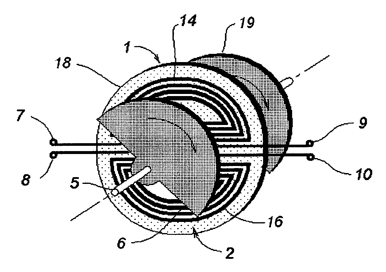
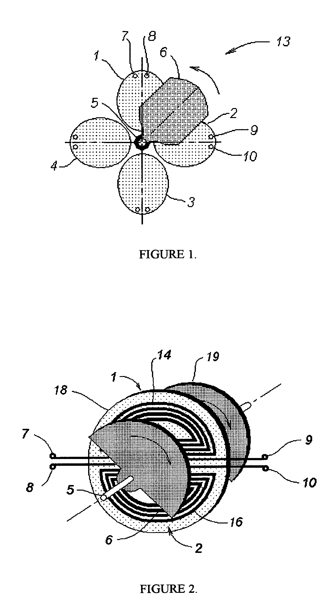
[0026]A general schematic of the present invention is shown in FIG. 1. Here, resonators 1, 2, 3, and 4 are placed in one plane (parallel to the rotation plane) perpendicular to a rotation axis, rotating rod 5. The number of resonators should exceed one. Electrodynamic target 6 connected to rotating rod 5 is installed in a rotation plane, having the capability of being rotated, and positioned parallel to the plane of the resonators. Its configuration is non-symmetrical with respect to the rotation axis. In all versions of the present invention, electrodynamic target 6 or an additional target positioned on the other side of resonators 1, 2, 3, and 4, should exhibit good electrical conductivity. It can be a metal plate or metallization on a dielectric plate, for example. Terminals of all resonators, e.g. terminals 7 and 8 of resonator 1 and terminals 9 and 10 of resonator 2, are connected to RF oscillator 11 and measuring circuit 12, shown later. All resonators mentioned above are form...


PUM


Abstract

An apparatus is disclosed for measuring a variable angular position of a movable part. The apparatus comprises at least two resonators formed by coupled slow-wave structures, and at least two movable targets having electrodynamic profiles, the targets also having a variable angular position. The angular position of the target is representative of the angular position of the movable part. An electromagnetic field is excited in the resonators at a frequency at which electromagnetic parameters of the resonators depend upon the position of the targets. A change in the angular position of the targets therefore causes a change in electrodynamic parameters of the resonators. The change in the electrodynamic parameters of the resonators is converted into a reading, such as an output voltage, which is indicative of the measured angular position.

Description

BACKGROUND OF THE INVENTION[0001]1. Field of the Invention[0002]The present invention relates to angular position measurement, more specifically, to an electromagnetic method and apparatus for measuring angular position, rotational speed, or displacement, of a movable target.[0003]2. Description of the Prior Art[0004]The usefulness of the application of an RF or microwave field for the measurement of angular position is recognized by the prior art. Such devices can operate with either RF or microwave excitation. When an electromagnetic field is excited near the rotating part of this type of device, the parameters of the electromagnetic field, such as resonant frequency, phase, or amplitude, vary with a change of angular position of the rotating part. The electromagnetic field parameters may be converted into a desired type of indication, including angle, angular displacement, angular speed, rotation frequency, and so on. In particular, such art is exemplified in U.S. Pat. No. 3,939,...

Claims


Application Information

Patent Timeline
Patent Type & Authority Patents(United States)
IPC IPC(8): G01R29/12G01P15/00
CPCG01D5/2225G01D5/202
Inventor PCHELNIKOV, YURIY NIKITICHNYCE, DAVID SCOTT
Owner NYCE DAVID S
Learn More