Power factor correction circuit

a technology of power factor and circuit, applied in the direction of power conversion systems, instruments, conversion with intermediate conversion to dc, etc., can solve the problems of heat generation and power loss in resistors becoming impediments, circuit constitution and control becomes complicated, etc., and achieves simple circuit constitution and inexpensive

Inactive Publication Date: 2015-05-12
MINEBEAMITSUMI INC
View PDF7 Cites 3 Cited by
  • Summary
  • Abstract
  • Description
  • Claims
  • Application Information

AI Technical Summary

Benefits of technology

[0008]The present invention has been made in view of the above-described problems, and an object of the present invention is to provide a power factor correction circuit in which the time point at which the reactor current becomes zero can be detected with an inexpensive and simple circuit constitution.
[0016]The power factor correction circuit according to the present invention is constituted as described above, and thus in the bridgeless power factor correction circuit, it is possible to detect the time point at which the reactor current becomes zero with an inexpensive and simple circuit constitution.

Problems solved by technology

However, for example, in a current detection technology using a current transformer, there has been a problem in that an additional circuit such as a reset circuit is necessary in order to achieve the necessary detection accuracy, and thus the circuit constitution and the control thereof becomes complicated.
In the case that a current detection resistor is connected to the reactor current path, heat generation and power loss in the resistor may become an impediment to miniaturization and efficiency improvement of the power factor correction circuit, and by extension the power supply apparatus itself.

Method used


Image

  • Power factor correction circuit
  • Power factor correction circuit
  • Power factor correction circuit

Examples


first embodiment

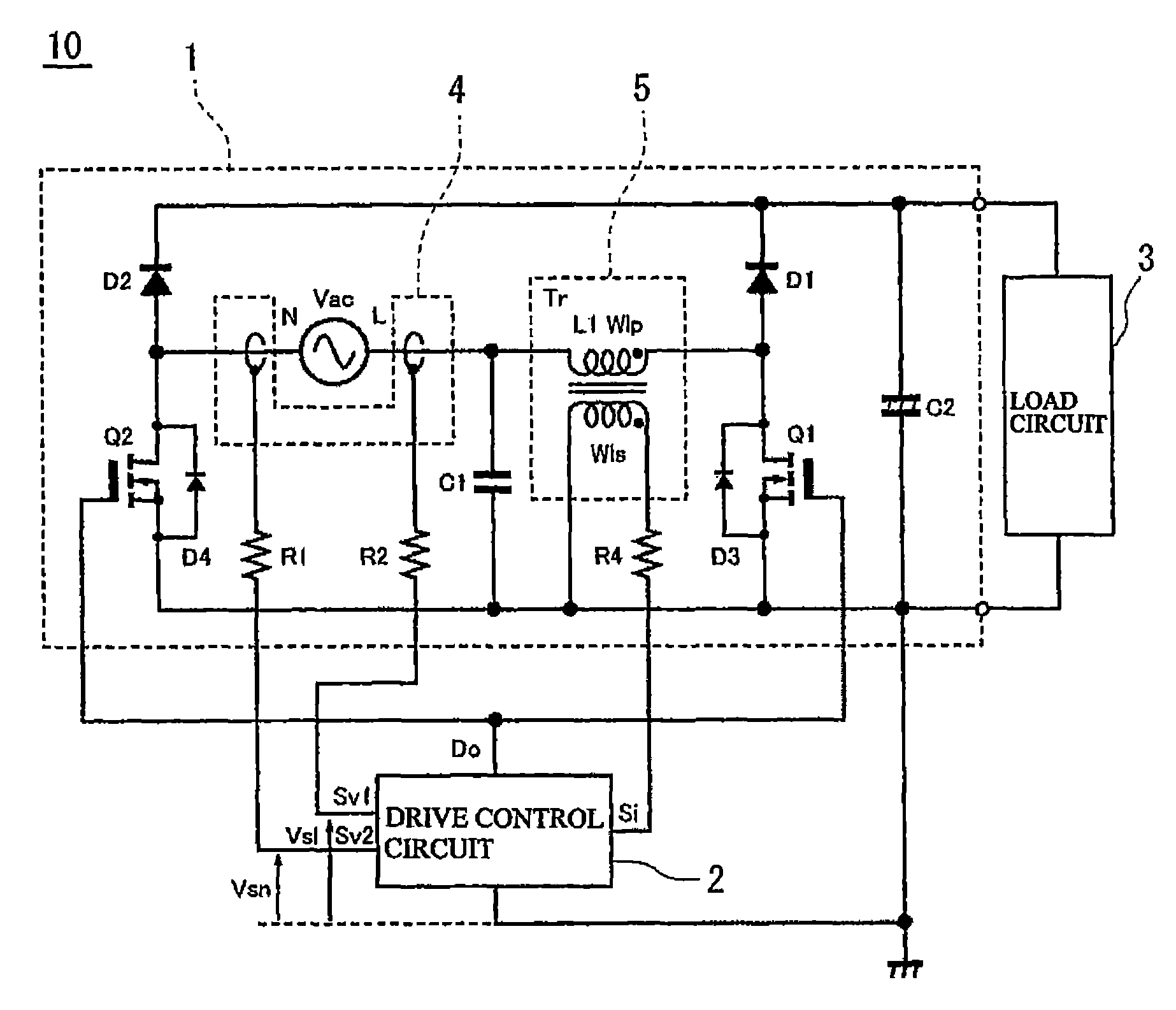
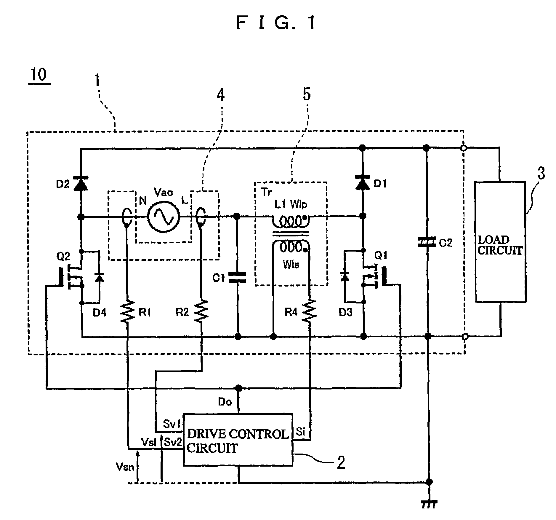
[0029]FIG. 1 is a circuit constitution diagram illustrating a power supply apparatus 10 including a power factor correction circuit 1 according to the present invention. In the power supply apparatus 10, the power factor correction circuit 1 functions to rectify, boost, and correct the power factor of an AC voltage of an AC power source Vac, and then apply it to a load circuit 3. The load circuit 3 is typically constituted by a DC-DC converter circuit or a DC-AC converter circuit, and the power factor correction circuit 1 constitutes an input stage of the power supply apparatus 10 that on the whole forms an AC-DC converter or an AC-AC converter. However, the present invention is not limited by the specific constitution of the load circuit 3, and any appropriate circuit can be used.

[0030]The power factor correction circuit 1 includes a first series circuit (indicated by reference numeral D1-Q1 when necessary) consisting of a first rectifier element D1 and a first switching element Q1...

second embodiment

[0073]FIG. 3 is a circuit constitution diagram illustrating a power supply apparatus 100 including a power factor correction circuit 1a according to the present invention. FIG. 4 is a waveform diagram illustrating the operation of the essential parts of the power factor correction circuit 1a.

[0074]The power factor correction circuit 1a differs from the power factor correction circuit 1 shown in FIG. 1 with respect to the following points. The power factor correction circuit 1a has a current detector 5a including a transformer Tra. The transformer Tra includes a primary winding Wlp that constitutes the reactor L1 and a first and second secondary winding Wls1 and Wls2 that are magnetically coupled to the primary winding Wlp. One end of each of the first and second secondary windings Wls1 and Wls2 is connected to the common line, the other end of the first secondary winding Wls1 is connected to a first reactor current detection terminal Si1 of a drive control circuit 2a via a resistor...

third embodiment

[0088]FIG. 5 is a circuit constitution diagram illustrating a power supply apparatus 200 including a power factor correction circuit 1b according to the present invention. FIG. 6 is a waveform diagram illustrating the operation of the essential parts of the power factor correction circuit 1b.

[0089]The power factor correction circuit 1b differs from the power factor correction circuit 1a shown in FIG. 3 in that the above-described switching unit is provided outside of a drive control circuit 2b as a switching circuit 6. The power factor correction circuit 1b is also an example in which an input voltage detector 4a is constituted so as to detect only an input voltage of the N-side terminal of the AC power source Vac.

[0090]In the power factor correction circuit 1b, the output end of the first secondary winding Wls1 of the transformer Tra is connected to the first reactor current detection terminal Si1 of the switching circuit 6 via the resistor R3, and the output end of the second sec...


PUM


Abstract

A power factor correction circuit includes a first series circuit, a second series circuit, a smoothing capacitor, and a reactor. The power factor correction circuit further includes an input voltage detector that detects an input voltage of at least one end of an AC power source based on one end on a ground side of the smoothing capacitor, and a current detector that detects a reactor current from the AC power source, the current detector having a transformer in which the reactor is a primary side, and first and second switching elements are controlled based at least partially on a reactor current detection signal that is output in accordance with the reactor current from a secondary side of the transformer to supply a desired DC voltage to a load circuit.

Description

BACKGROUND OF THE INVENTION[0001]1. Field of the Invention[0002]The present invention relates to a power factor correction circuit, and particularly to a critical mode operation of a bridgeless power factor correction circuit.[0003]2. Description of the Related Art[0004]Conventionally, in order to supply electric power to a load, a power source apparatus in which an AC (alternating current) voltage from an input AC power source is rectified and then converted to a desired AC or DC (direct current) voltage and supplied to the load has been widely used. In this kind of power source apparatus, a power factor correction circuit needs to be provided in order to correct the power factor and reduce the EMI noise generated by the power source apparatus. Therefore, in a general constitution of a power supply apparatus, a rectification circuit consisting of a diode bridge and a power factor correction circuit consisting of a boost converter circuit are installed in the input stage.[0005]In re...

Claims


Application Information

Patent Timeline
Patent Type & Authority Patents(United States)
IPC IPC(8): G05F1/56G05F1/70
CPCG05F1/70
Inventor NISHIBORI, KOHEICHALERMBOON, NADTHAWUT
Owner MINEBEAMITSUMI INC
Why Eureka
Try Eureka