Lens barrel, camera module, and imaging apparatus

a technology for imaging apparatus and lens barrel, which is applied in the direction of printers, instruments, camera focusing arrangement, etc., can solve the problems of reducing affecting the external size of the lens barrel, and difficult to secure a space for the magnet, so as to reduce the overall size, weight and cost, and increase the size of the magnet

Active Publication Date: 2012-10-23
SONY CORP
View PDF9 Cites 20 Cited by
  • Summary
  • Abstract
  • Description
  • Claims
  • Application Information

AI Technical Summary

Benefits of technology

[0010]In view of the foregoing, it is desirable to provide a lens barrel, a camera module, and an imaging apparatus with a reduced overall size achieved without reducing the thrust for a lens holding member on the side of a movable portion.
[0015]According to the embodiments of the present invention, the cover member is magnetic, and thus functions as a yoke. The magnet is directly attached at a position facing the drive coil. According to the embodiments of the present invention, a yoke which is used in the related art is not necessary, which contributes to reducing the overall size, weight, and cost. In addition, it is possible to increase the size of the magnet and hence the drive force of a voice coil motor.

Problems solved by technology

Thus, the size of the magnet significantly affects the external size of the lens barrel.
Therefore, in view of the circumstances in which it is desirable to reduce the size of the entire lens barrel, it may be difficult to secure a space for the magnet.
It may also be difficult to secure a space for a yoke, which is used together with the magnet.

Method used


Image

  • Lens barrel, camera module, and imaging apparatus
  • Lens barrel, camera module, and imaging apparatus
  • Lens barrel, camera module, and imaging apparatus

Examples


Embodiment Construction

[0032]A camera module installed in a cellular phone according to an embodiment of the present invention will be described below in the following order with reference to the drawings.

[0033]1. Cellular Phone

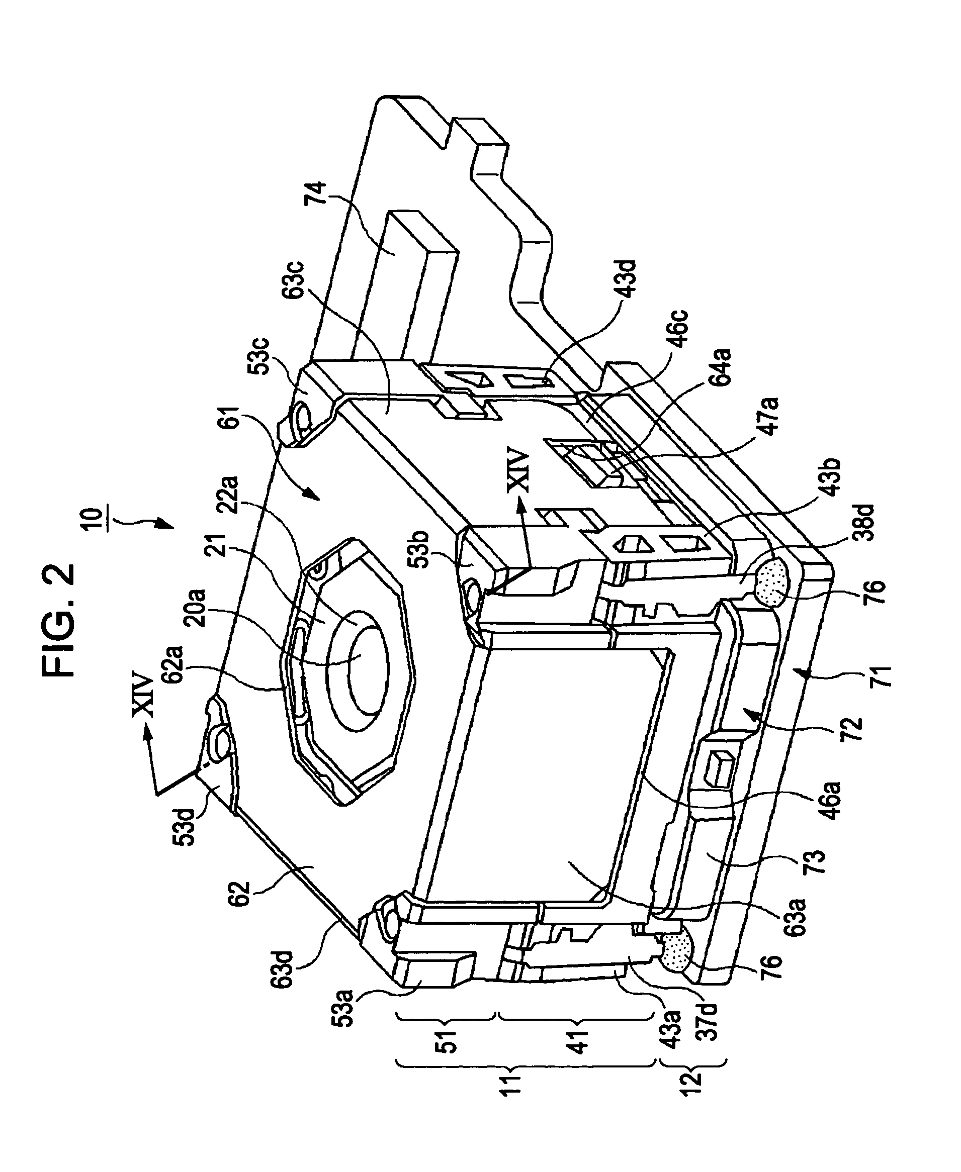
[0034]2. Camera Module

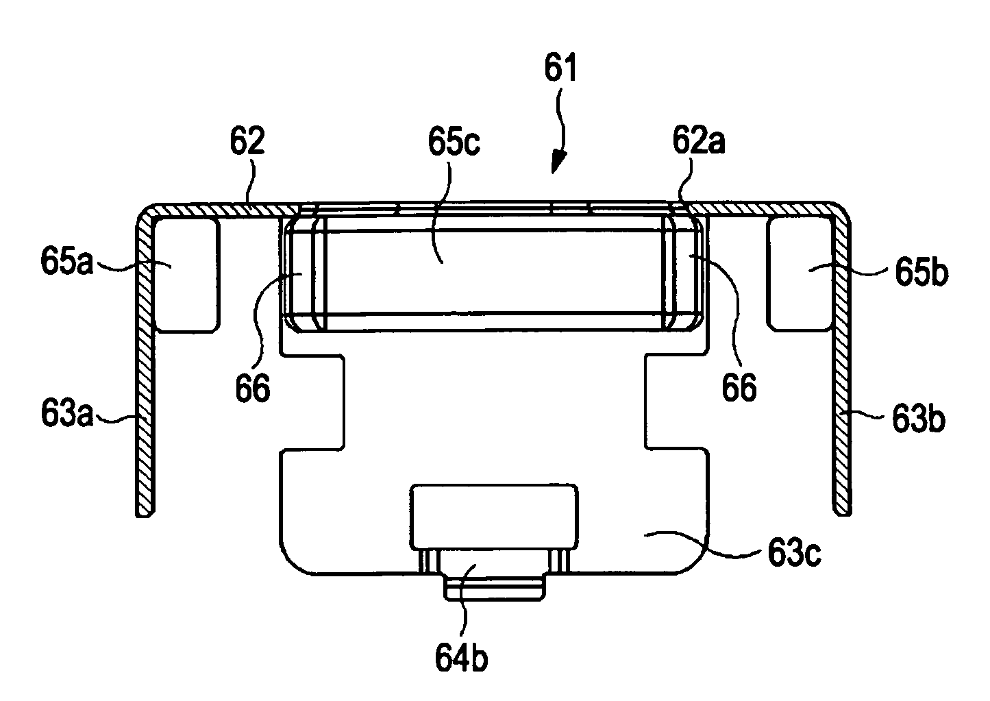
[0035]3. Lens Barrel[0036]3-1. Lens Holding Member[0037]3-2. Drive Coil[0038]3-3. Flexible Wiring Circuit Board[0039]3-4. Plate Spring[0040]3-5. Rear Barrel[0041]3-6. Front Barrel[0042]3-7. Cover Member

[0043]4. Imaging Element Portion

[0044]5. Assembly of Camera Module

[0045]6. Operation of Camera Module

[0046]7. Effect of Camera Module

[0047]8. Modifications
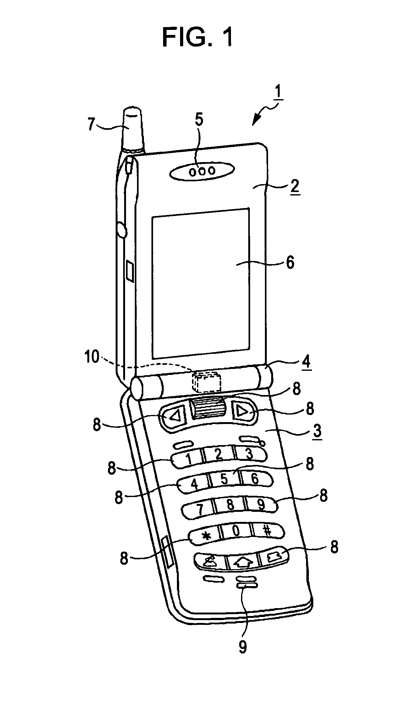
(1. Cellular Phone)

[0048]As shown in FIG. 1, a cellular phone 1 equipped with a camera module according to an embodiment of the present invention includes a first housing 2 and a second housing 3 coupled with each other via a hinge portion 4 so as to be foldable. The first housing 2 is provided with a speaker 5, a display 6, and an antenna 7. The antenna 7 is expandable / retractable. The second housing 3 is pro...


PUM


Abstract

A lens barrel includes: a lens holding member that holds a lens; a drive coil attached to an outer peripheral portion of the lens holding member; a magnet attached to face the drive coil; a barrel member in which the lens holding member is disposed; and a cover member attached to the barrel member with the lens on a light incident side of the lens holding member facing to an outside. The cover member is magnetic, and the magnet is directly attached to the cover member at a position acing the drive coil.

Description

CROSS-REFERENCE TO RELATED APPLICATION[0001]The present application claims priority from Japanese Patent Application No. JP 2009-189589 filed in the Japanese Patent Office on Aug. 18, 2009, the entire content of which is incorporated herein by reference.BACKGROUND OF THE INVENTION[0002]1. Field of the Invention[0003]The present invention relates to a lens barrel for an imaging apparatus incorporated in a small electronic device such as a portable terminal device. More specifically, the present invention related to a lens barrel for an imaging apparatus, a camera module, and an imaging apparatus that use a voice coil motor in a focus drive mechanism.[0004]2. Description of the Related Art[0005]Most imaging apparatuses installed in cellular phone terminals are equipped with an auto-focus function. In order to use the auto-focus function, it is necessary to move a group of optical lenses inside in an optical-axis direction. As a mechanism that drives the group of lenses, voice coil mot...

Claims


Application Information

Patent Timeline
Patent Type & Authority Patents(United States)
IPC IPC(8): G03B3/10
CPCG02B7/08H04N5/2257H04N5/2254H04N5/2253H04N23/54H04N23/57H04N23/55
Inventor YOSHIDA, KYOSUKETAKAHASHI, YASUTAKAFUJISHIRO, FUMIHIKO
Owner SONY CORP
Why Eureka
Try Eureka