Stackable pieces of flatware

a flatware and stacking technology, applied in the field of stacking cutlery elements, can solve the problems of inability to re-use the principle of cutlery elements, inability to achieve stack density, and inability to achieve the shape of cutlery elements, so as to facilitate automatic centering of individual cutlery elements, reduce the risk of becoming stuck, and facilitate the effect of automatic centering

Active Publication Date: 2012-10-30
FOSTAG FORMENBAU
View PDF16 Cites 45 Cited by
  • Summary
  • Abstract
  • Description
  • Claims
  • Application Information

AI Technical Summary

Benefits of technology

[0009]One object of this invention is to provide stackable cutlery elements of the type mentioned above which do not suffer from the disadvantages mentioned above and other disadvantages, and allows, in particular, high stacking density together with minimum material consumption.
[0012]To achieve maximum stability, the handle of the cutlery element of this invention is designed as a wall with longitudinal ribs arranged on both sides of it in the edge region so that an essentially H-shaped cross-section is obtained. For additional stabilization, an end rib is arranged on both sides of the wall on the longitudinal end of the handle opposing the functional element.
[0014]The end rib and the longitudinal ribs of the handle of a cutlery element of this invention are advantageously designed so that the ribs have a first bevel on the first side of the wall or handle on the outer edge, such as on the edge of the ribs facing away from the wall. On the second side of the wall or handle the end rib and the longitudinal ribs have a second bevel on an inner edge facing the wall. This advantageous embodiment facilitates automatic centering of the individual cutlery elements of this invention when they are stacked. The demands for the required precision of production of the cutlery elements of this invention are also less as a result of adopting such a solution, which is advantageous for cost reasons.
[0015]In an even more advantageous embodiment of a cutlery element of this invention, the angle of inclination of the second bevel to the plane of the wall is smaller than the angle of inclination of the first bevel to the plane of the wall. The thus additional advantageous effect is that the points of contact of cutlery elements of this invention, stacked one on top of the other, are limited to the outer edge of the ribs of the first side. The individual sections can then be detached more easily from each other and the risk of becoming stuck is even lower.

Problems solved by technology

The shaping of the cutlery elements and the stack density that can be achieved are in this case limited because of the U-shaped design of the handle.
Also, the individual cutlery elements may become stuck due to the wedge shape of the handles.
The user must in each case irreversibly break off one cutlery element from the packaging unit by exerting force, which means that this arrangement is in principle not suitable for re-usable cutlery elements.

Method used


Image

  • Stackable pieces of flatware
  • Stackable pieces of flatware
  • Stackable pieces of flatware

Examples


Embodiment Construction

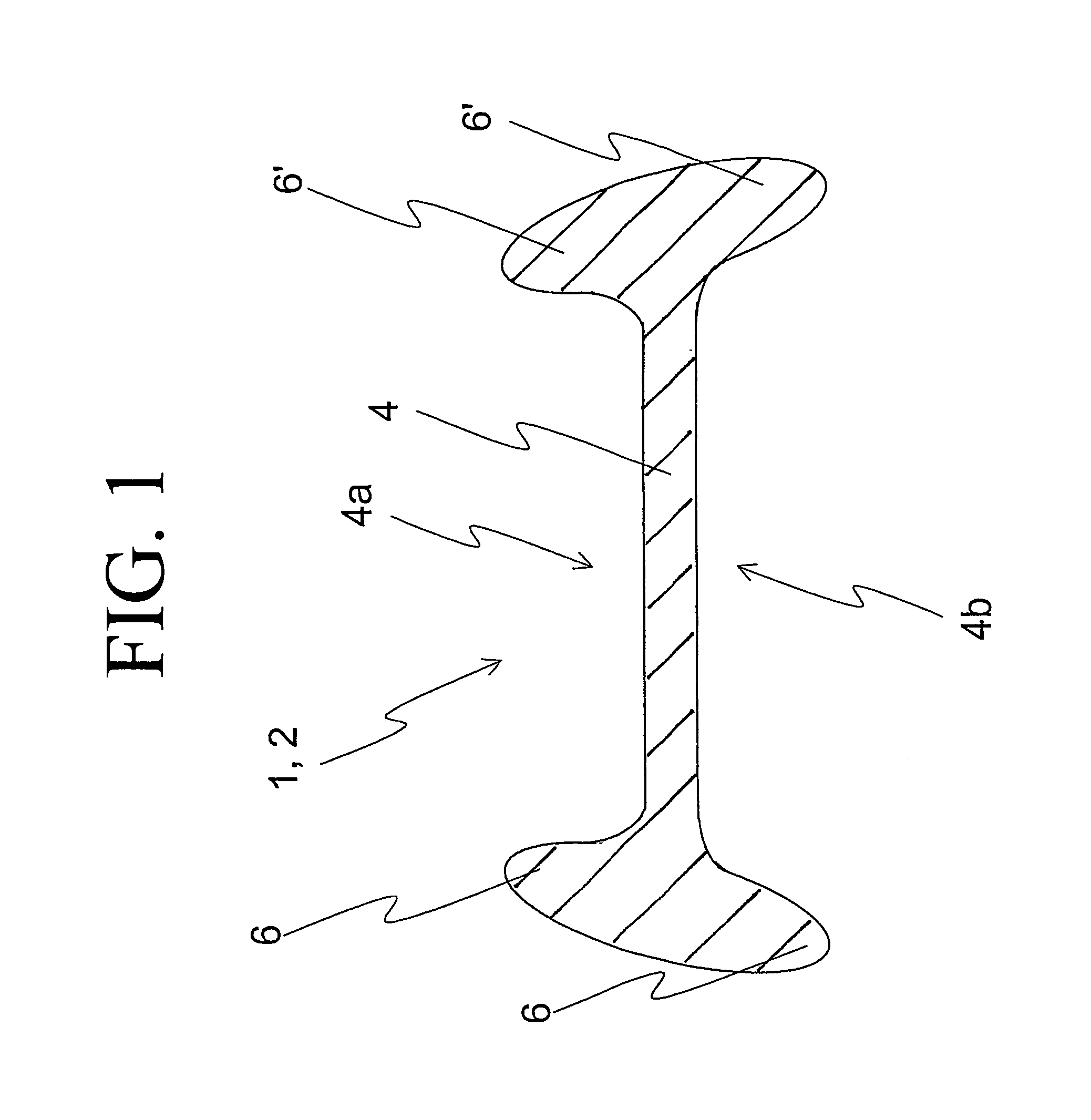
[0029]FIG. 1 explains the structure of a cutlery element 1 of this invention with reference to a cross-section perpendicular to the longitudinal axis of handle 2 of cutlery element 1. Longitudinal ribs 6, 6′ are shaped on the edges of the first side 4a and second side 4b of the wall 4 of handle 2.

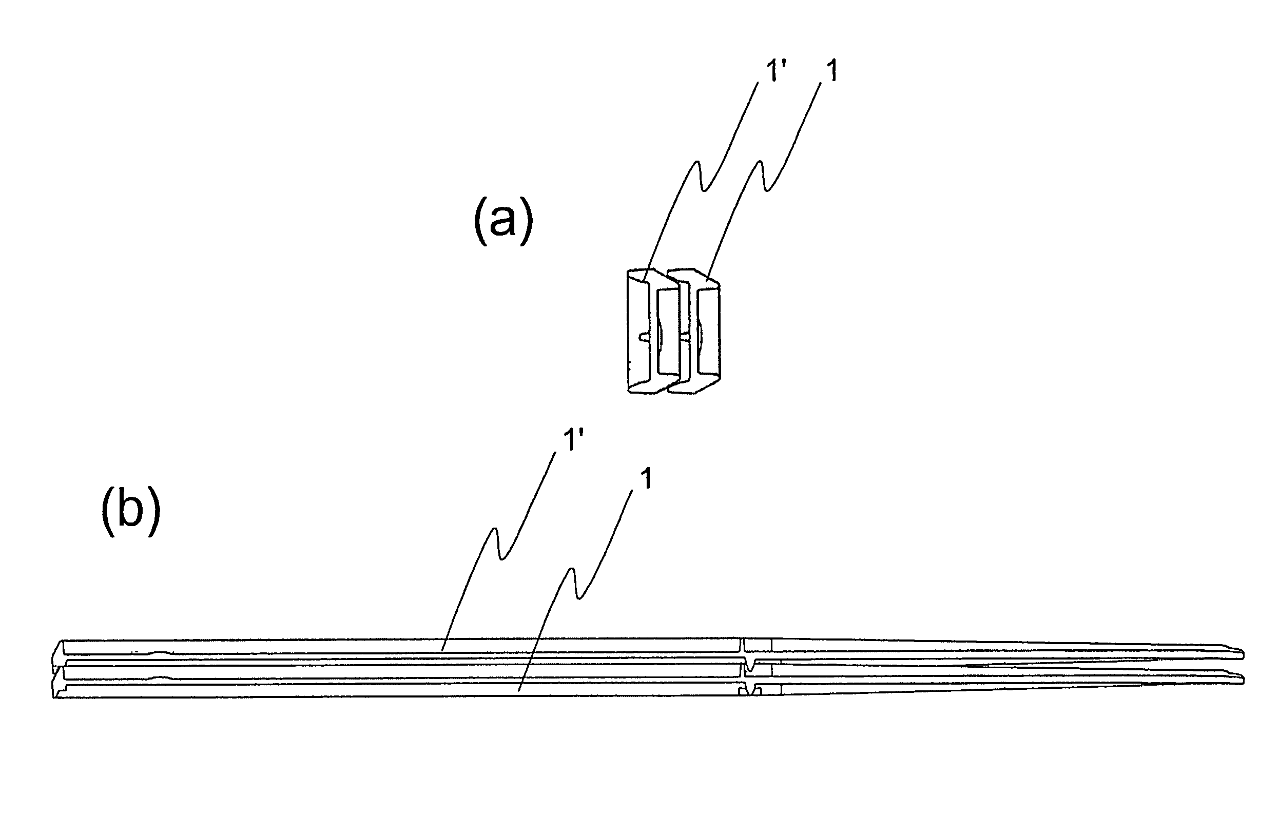
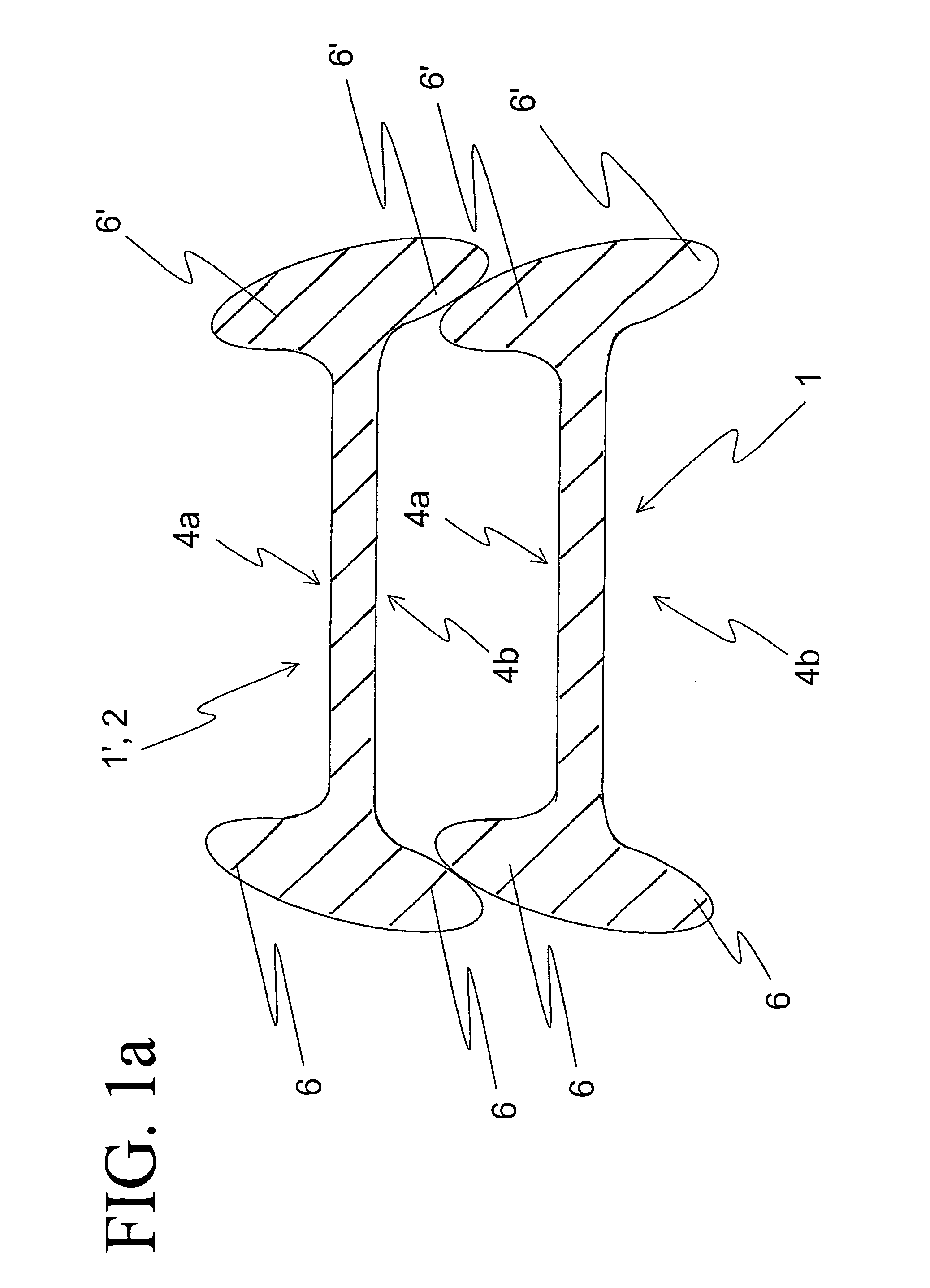
[0030]As shown in FIG. 1a, the longitudinal ribs are designed so that when cutlery elements 1, 1′ of this invention are stacked, ribs 6, 6′ of first side 4a of a cutlery element 1 engage positively in ribs 6, 6′ of second side 4b of the other cutlery element 1′. The same applies to the end ribs not shown in cross-section.

[0031]FIGS. 2 and 2a show a further embodiment of a cutlery element 1 of this invention, in a cross-section taken through handle 2. Longitudinal ribs 6, 6′ are arranged at right angles to the wall. Longitudinal ribs 6, 6′ of first side 4a are offset toward the inside in relation to longitudinal ribs 6, 6′ of second side 4b. When cutlery elements 1, 1′ of this invention are ...


PUM


Abstract

A stackable cutlery element having a handle and a functional element shaped onto the handle. To achieve maximum stability, the handle of the cutlery element is designed as a wall with longitudinal ribs arranged on the edge of both sides, so that an essentially H-shaped cross-section is formed. For additional stabilization, an end rib is arranged on the longitudinal end of the handle opposing the functional element on both sides of the wall. The end rib and the two longitudinal ribs on both sides are designed so that when the cutlery elements of this invention are stacked, the end rib and the longitudinal ribs of the first side of a cutlery element engage positively in the end rib and longitudinal ribs of the second side of the further cutlery element to connecting to them in the stacking direction.

Description

BACKGROUND OF THE INVENTION[0001]1. Field of the Invention[0002]This invention relates to a stackable cutlery element with a handle with a wall and a functional element shaped onto the handle.[0003]2. Discussion of Related Art[0004]Cutlery of plastic, in particular knives, spoons and forks, are widely used whether as disposable cutlery for single use or in places where plastic cutlery is preferred to metal cutlery for reasons of weight and safety, for example in an aircraft. Because cutlery elements are manufactured with relatively thin walls, for reasons of cost and weight, sufficient stability is achieved by suitable shaping. For example, handles with a T-shaped, H-shaped, S-shaped or U-shaped cross-section are conventionally used.[0005]It may be desirable to stack several cutlery elements, for example for simpler erection of packaging units or for space-saving storage, particularly of cutlery elements intended for multiple use.[0006]The state of the art provides different solutio...

Claims


Application Information

Patent Timeline
Patent Type & Authority Patents(United States)
IPC IPC(8): A47G21/02
CPCA47G21/02
Inventor MUEHLEMANN, ROLF
Owner FOSTAG FORMENBAU
Why Eureka
Try Eureka