
Personal authentication apparatus and method

a technology of authentication apparatus and authentication method, which is applied in the direction of program control, testing/monitoring control system, instruments, etc., can solve the problems of affecting the quality affecting the accuracy of personal authentication apparatus, and unable to ensure the adequate set-up location of products, etc., to achieve the effect of suppressing the diffraction of light and avoiding the crushing of vein pattern

Active Publication Date: 2012-10-30
HITACHI ASTEMO LTD
View PDF18 Cites 4 Cited by
  • Summary
  • Abstract
  • Description
  • Claims
  • Application Information

AI Technical Summary

Benefits of technology

The present invention provides a finger-vein authentication apparatus that is small-size and thin-type, but still has good imaging quality and is secure against external light. The apparatus includes a light source and an image sensor positioned at the sides of a fingertip with a nail sandwiched between them. A fingertip guidance jig and a finger-root guidance jig are set up to support the fingertip and the finger-root, respectively. An empty clearance is provided at a position under the half-plane of the finger on the imaging-plane side to avoid crushing the vein pattern due to pressure applied onto the imaging plane by touching the structure with the finger. A light-shielding unit is set up on the light-source side to suppress the diffraction of light from the light-source side. These features make the apparatus convenient for users and enhance security.

Problems solved by technology

Depending on the products into which the finger-vein authentications are to be installed, however, many of the products find it difficult to ensure their adequate set-up locations.
No sufficient consideration, however, has been given to a factor of reducing thickness of the entire apparatus configured by such components as the light source and camera gathered to the finger's ball-side.
No study, however, has been made to thin-type and small-size implementation of the entire apparatus.
Accordingly, it cannot be said that sufficient consideration has been given to the imaging quality.
Consequently, there has existed a concern of exerting a bad influence on the authentication accuracy as well.

Method used


Image

  • Personal authentication apparatus and method
  • Personal authentication apparatus and method
  • Personal authentication apparatus and method

Examples


Embodiment Construction

[0025]Hereinafter, the explanation will be given below concerning embodiments of the present invention.

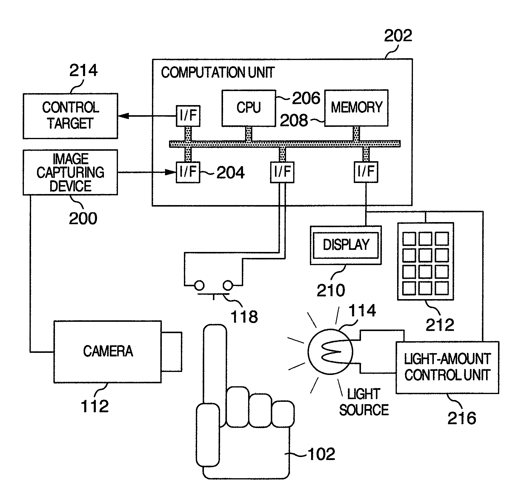
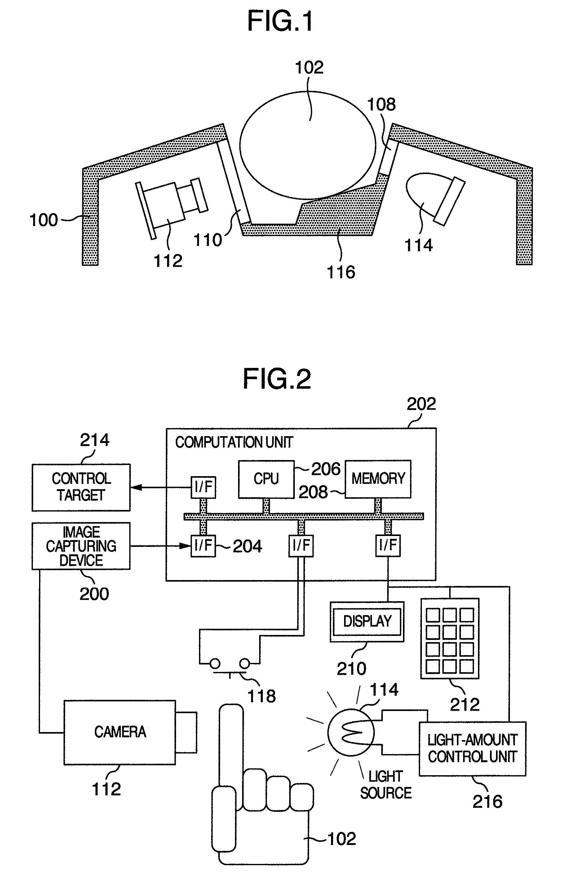
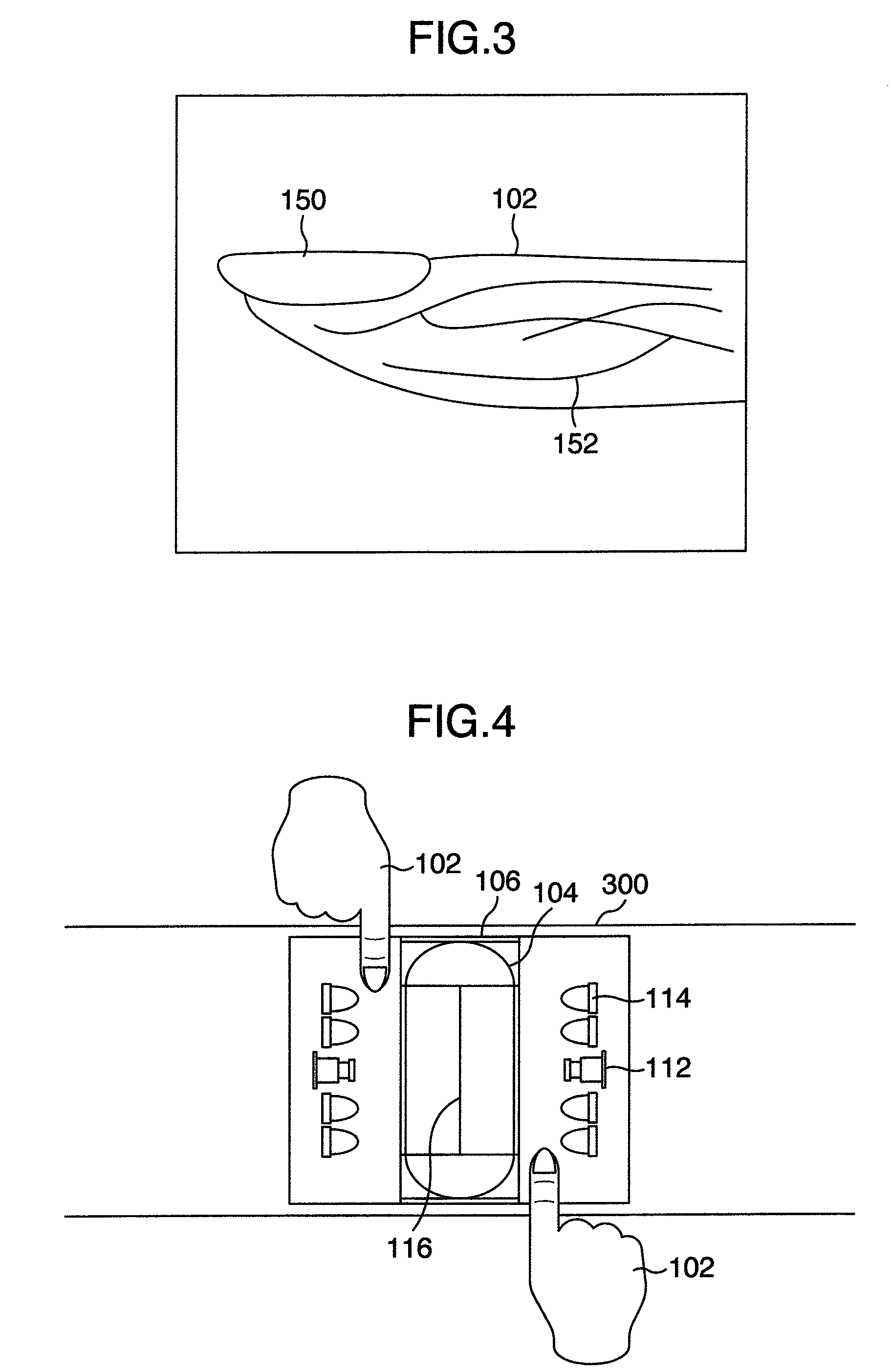
[0026]FIG. 1 is a schematic diagram of the authentication apparatus according to a first embodiment of the present invention. A housing 100 includes a groove-shaped structure therein. By this groove, a location on which a finger is to be placed is presented in a manner of being readily recognizable intuitively. A light source 114 is disposed on one of the right and left sides of the groove. An image sensor (i.e., camera) 112 is disposed on the other side thereof in a manner of being opposed to the light source 114. If the present authentication apparatus is set up at a location which is difficult to recognize visually from the user, this groove plays a role of a three-dimensional guiding mechanism for permitting the user to gropingly confirm the location on which the finger is to be placed. Simultaneously, this groove also has a function as a light-shielding side wall which is low ...


PUM


Abstract

There is provided a finger-vein authentication apparatus including a light source for illuminating one surface of both side-surfaces of a fingertip of a finger with light, and an image sensor for imaging the other surface of the fingertip, the light source and the image sensor being positioned at both sides of a nail of the fingertip with the nail sandwiched therebetween, wherein a fingertip guidance jig for supporting the fingertip and a finger-root guidance jig for supporting a finger-root of the finger are disposed between the light source and the image sensor, a light-shielding unit being disposed on the light-source side, the light-shielding unit being used for shielding the illumination light such that the illumination light will not travel to a ball side of the finger.

Description

INCORPORATION BY REFERENCE[0001]The present application claims priority from Japanese application JPA-2007-262845 filed on Oct. 9, 2007, the content of which is hereby incorporated by reference into this application.BACKGROUND OF THE INVENTION[0002]The present invention relates to a personal authentication apparatus using a living body. More particularly, it relates to a biometric personal authentication apparatus based on the vein pattern of a finger.[0003]In recent years, attention has been focused on biometric authentications as security schemes where carrying a key or the like is unnecessary, a high convenience is accomplished, and there is a less danger of being illegally exercised by being lost or stolen. In these biometric authentications, a part of the body of an individual person, such as fingerprint, iris, or vein pattern, is used as the key. Of these biometric authentications, in the authentication methods using the vein pattern of a finger, criminal investigation is not ...

Claims


Application Information

Patent Timeline
Patent Type & Authority Patents(United States)
IPC IPC(8): G06K9/00G05B19/00
CPCG07C9/00158G07C9/00563G07C9/37
Inventor NAGASAKA, AKIOMATSUMURA, TAKAFUMIHAYASHI, MASAHIDEMIYATAKE, TAKAFUMIMIURA, NAOTOKIYOMIZU, HARUMI
Owner HITACHI ASTEMO LTD
Learn More