Embolic protection system

a protection system and embolism technology, applied in the field of embolism protection systems, can solve the problems of severely restricted space available for the deployment of distal filters and the inability to use conventional integrated devices, and achieve the effect of facilitating practical implementation

Inactive Publication Date: 2012-11-06
SALVIAC
View PDF24 Cites 10 Cited by
  • Summary
  • Abstract
  • Description
  • Claims
  • Application Information

AI Technical Summary

Benefits of technology

[0008]There is therefore a need for an improved integrated system which has the advantage of a treatment device, such as a stent, and a

Problems solved by technology

However, in clinical practice the site to be treated is often difficult to access and the space available for deployme

Method used


Image

  • Embolic protection system
  • Embolic protection system
  • Embolic protection system

Examples


Embodiment Construction

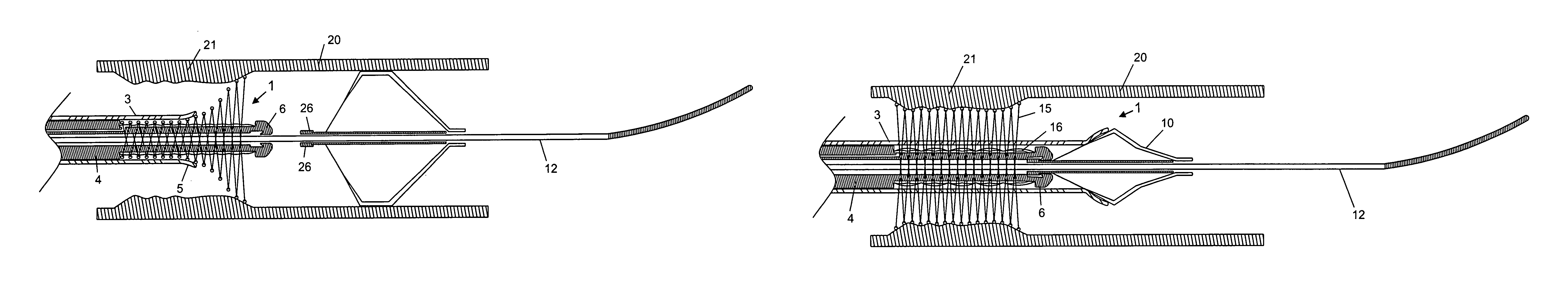
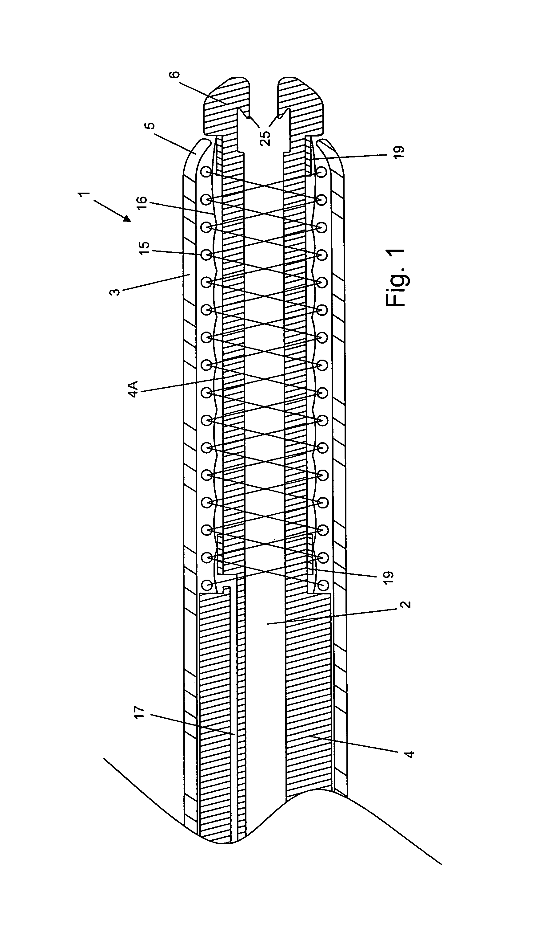
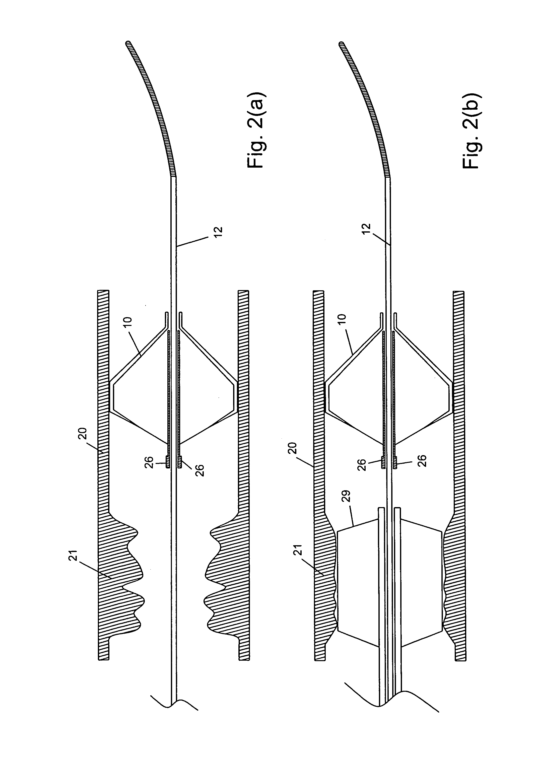
[0143]Referring to the drawings there is illustrated a catheter according to the invention. The catheter has an internal reception space for receiving an embolic protection filter to enable the filter to be transported through a vasculature, and the catheter comprises means to facilitate treatment of a site in the vasculature.

[0144]The catheters of the invention facilitate carrying our at least two procedures using a single catheter. In some cases the catheter facilitates delivery of an embolic protection device distal to a treatment location and carrying out a procedure at the treatment site such as an angioplasty or deployment of a stent. In other cases the catheter facilitates carrying out of a procedure at the treatment site such as an angioplasty or a stent deployment and subsequent retrieval of the embolic protection device into the same catheter completion of the procedure.

[0145]The embolic protection device may comprise a filter such as those described in International paten...


PUM


Abstract

A catheter system 1 has an internal reception space for an embolic protection filter 10 to enable the filter 10 to be transported through a vasculature 20 and a treatment means such as a stent 15 to facilitate treatment. The catheter system may be used for retrieval of a filter 10 and stenting of a lesion with a stent 15. The procedure may also involve post dilatation using an on-board balloon 16.

Description

CROSS REFERENCE TO RELATED APPLICATIONS[0001]This application claims the benefit of U.S. Provisional Application Nos. 60 / 379,396 filed May 13, 2002; and 60 / 412,545, filed Sep. 23, 2002, the contents of both of which are incorporated herein by reference.INTRODUCTION[0002]This invention relates to a catheter, in particular to a catheter for transporting an embolic protection filter through a vasculature.[0003]During an interventional procedure, it is known to deploy an embolic protection filter distally of a treatment site in a vasculature using a delivery catheter. The filter is used to capture any embolic material generated during a treatment procedure subsequently performed at the treatment site. After completion of the treatment procedure the filter and the captured embolic material are retrieved from the vasculature using a retrieval catheter.[0004]This invention is aimed at providing a catheter which enables an interventional procedure of this type to be carried out with greater...

Claims


Application Information

Patent Timeline
IPC IPC(8): A61F2/01A61F2/00A61F2/06A61F2/84
CPCA61F2/013A61F2/95A61F2002/011A61F2210/0057A61F2250/0019A61F2230/0084A61F2002/018A61F2230/0006A61F2230/005A61F2/011A61F2/966A61F2/014A61F2/9522A61F2/844
Inventor BRADY, EAMONTAYLOR, CHARLESGRIFFIN, PATRICKCASEY, BRENDANVALE, DAVIDGILSON, PAULO'SHAUGHNESSY, JOHN
Owner SALVIAC
Why Eureka
Try Eureka