Superconductive magnet
a superconductive magnet and superconductive technology, applied in the direction of superconducting magnets/coils, magnetic bodies, instruments, etc., can solve the problems of increasing the amount of materials used, weight and the cost of production, cooling, transportation, etc., and achieve the effect of reducing the amount of materials and machining costs
- Summary
- Abstract
- Description
- Claims
- Application Information
AI Technical Summary
Benefits of technology
Problems solved by technology
Method used
Image
Examples
embodiment 1
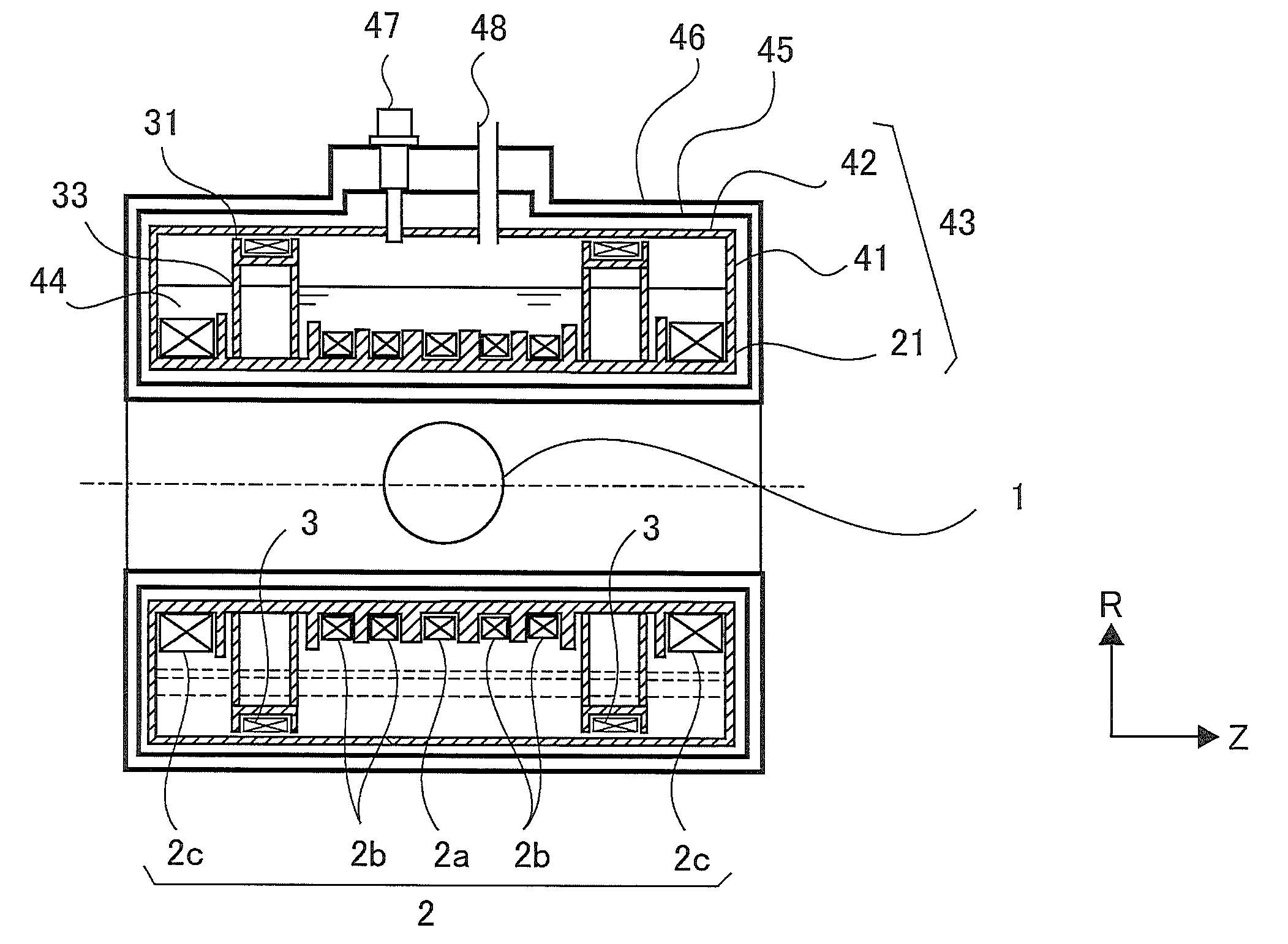
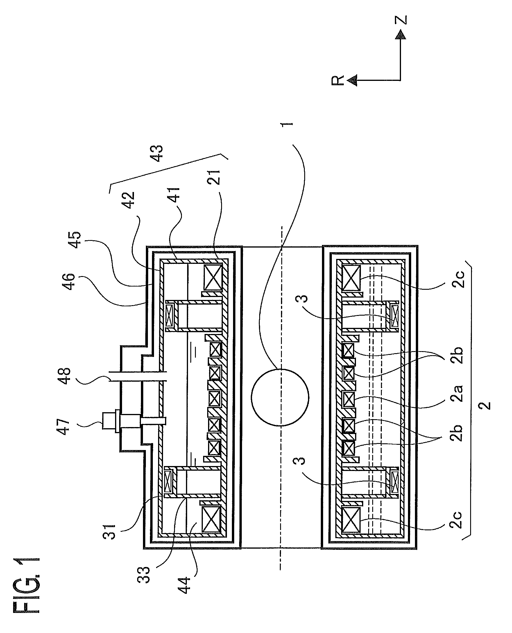
[0029]FIG. 1 is a cross-sectional view, taken along a plane parallel to the Z axis, of a superconductive magnet according to Embodiment 1 of the present invention. In addition, in each of the figures, the same reference marks indicate the same or equivalent constituent elements, and some of explanations therefor will be omitted. In FIG. 1, reference numeral 1 denotes a magnetic-field generation region where a magnetic field is produced; reference numeral 2 denotes a main coil for generating a desired magnetic field in the magnetic-field generation region 1; reference numeral 3 denotes a shield coil for cancelling a magnetic field that leaks outward. The shield coil 3 is disposed in such a way as to be coaxial with the Z axis of the main coil 2 and more distal than the main coil 2 from the Z axis (the radial distance between the Z axis and the center of the shield coil 3 is larger than the radial distance between the Z axis and the center of the main coil 2). The main coil 2 and the ...
embodiment 2
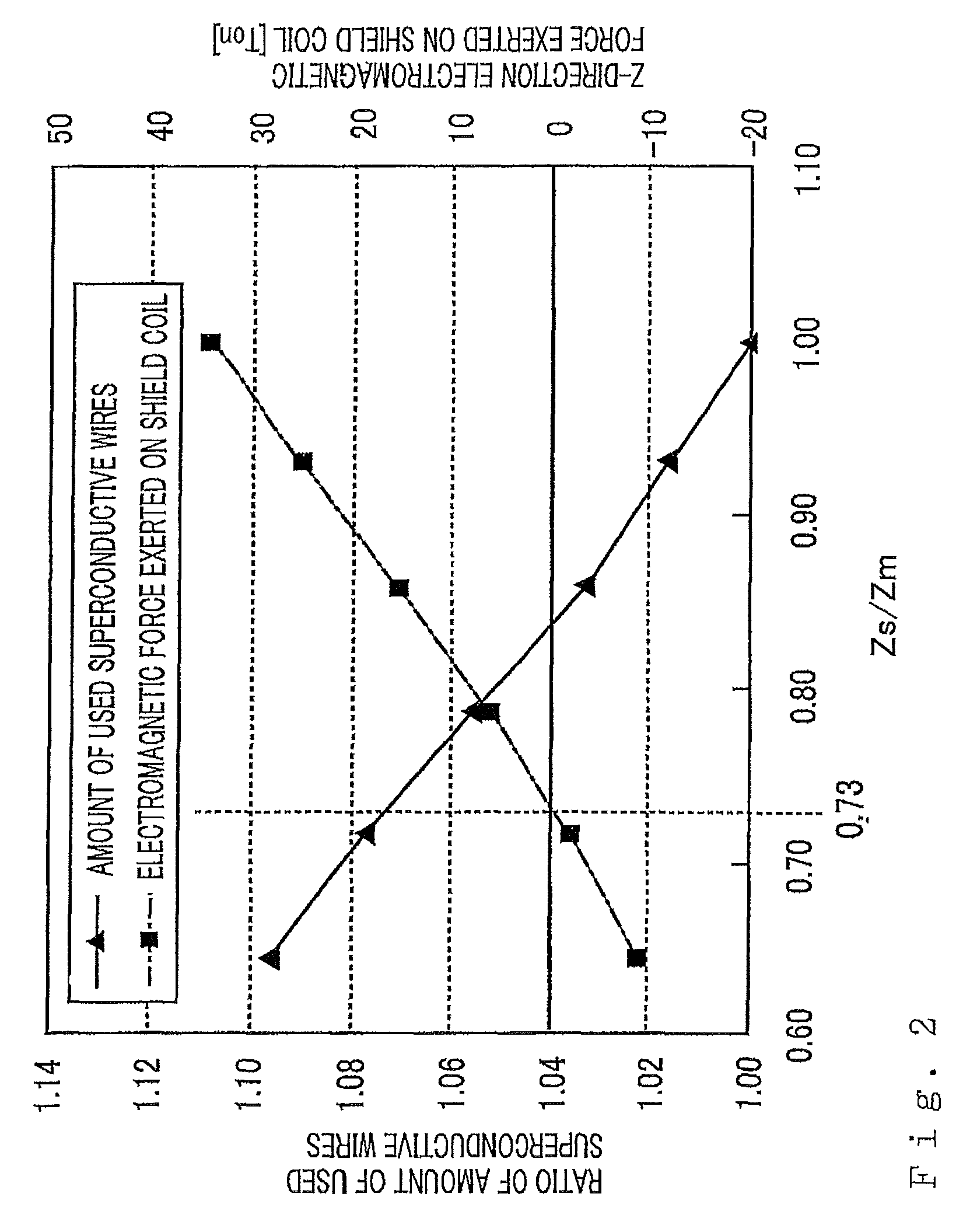
[0041]FIG. 4 is a cross-sectional view, taken along a plane parallel to the Z axis, of a superconductive magnet according to Embodiment 2. FIG. 5 is a cross-sectional view, taken along a plane perpendicular to the Z axis, of the superconductive magnet in FIG. 4. The superconductive magnet according to Embodiment 2 is similar to the superconductive magnet according to Embodiment 1 in that there are included a main coil 2, a main bobbin 21, shield coils 3, shield bobbins 31, helium tank flanges 41, a helium tank outer cylinder 42, a thermal shield 45, a vacuum tank 46, a refrigerator 47, and a service port 48. The arrangement of the shield coil 3 is similar to the superconductive magnet according to Embodiment 1 in that Zs / Zm is made to be approximately 0.73, in order to arrange the shield coil 3 at a position where the Z-direction electromagnetic force exerted on the shield coil 3 is minimized while the increase in the amount of used superconductive wires is suppressed.
[0042]A shield...
embodiment 3
[0044]FIG. 6 is a cross-sectional view, taken along a plane parallel to the Z axis, of a superconductive magnet according to Embodiment 3. FIG. 7 is a cross-sectional view, taken along a plane perpendicular to the Z axis, of the superconductive magnet in FIG. 6. The superconductive magnet according to Embodiment 3 is similar to the superconductive magnet according to Embodiment 1 in that there are included a main coil 2, a main bobbin 21, shield coils 3, shield bobbins 31, helium tank flanges 41, a helium tank outer cylinder 42, a thermal shield 45, a vacuum tank 46, a refrigerator 47, and a service port 48. The arrangement of the shield coil 3 is similar to the superconductive magnet according to Embodiment 1 in that Zs / Zm is made to be approximately 0.73, in order to arrange the shield coil 3 at a position where the Z-direction electromagnetic force exerted on the shield coil 3 is minimized while the increase in the amount of used superconductive wires is suppressed.
[0045]In Embod...
PUM
| Property | Measurement | Unit |
|---|---|---|
| diameter | aaaaa | aaaaa |
| magnetic field | aaaaa | aaaaa |
| magnetic field | aaaaa | aaaaa |
Abstract
Description
Claims
Application Information
 - R&D
- Intellectual Property
- Life Sciences
- Materials
- Tech Scout
- Unparalleled Data Quality
- Higher Quality Content
- 60% Fewer Hallucinations
Browse by: Latest US Patents, China's latest patents, Technical Efficacy Thesaurus, Application Domain, Technology Topic, Popular Technical Reports.
© 2025 PatSnap. All rights reserved.Legal|Privacy policy|Modern Slavery Act Transparency Statement|Sitemap|About US| Contact US: help@patsnap.com


