
Channel characteristic analyzing apparatus and method

a channel characteristic and characteristic analysis technology, applied in the direction of electrical apparatus, transmission monitoring, modulation, etc., can solve problems such as deteriorating transmission quality, and achieve the effect of appropriate propagation path modeling

Inactive Publication Date: 2012-11-06
NAT INST OF INFORMATION & COMM TECH
View PDF10 Cites 10 Cited by
  • Summary
  • Abstract
  • Description
  • Claims
  • Application Information

AI Technical Summary

Benefits of technology

The patent text describes a problem in analyzing the propagation path of radio signals in the millimeter wave band, especially when the positions of the communication terminals are not known in advance. The conventional over-the-horizon multipath propagation path model is not suitable for this situation, so a stochastic approach is needed to model the propagation path. The technical effect of the patent text is to provide a data transmission characteristic analysis apparatus that takes into consideration the propagation channel characteristic when a reception apparatus receives a radio signal of a millimeter wave band, via a reception antenna of a transmission apparatus, via a reception antenna of a reception apparatus. This apparatus uses a two-wave model to handle the position parameters needed in the model, and stochastically processes them to ensure accurate modeling of the millimeter wave propagation path.

Problems solved by technology

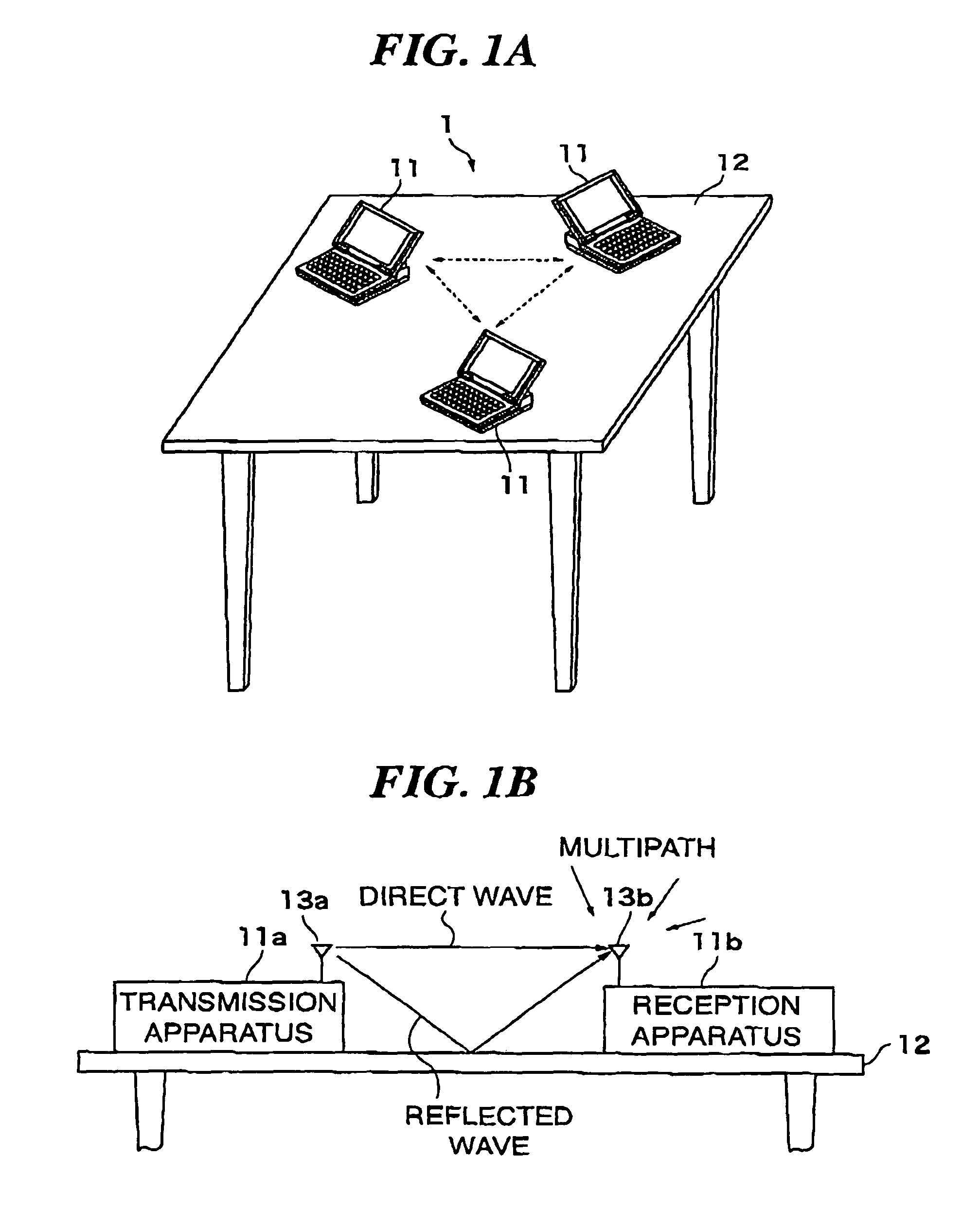
That is, the propagation paths from one terminal unit to the other terminal units become a so-called multipath (multiplex transmission path), which deteriorates the transmission quality, may eventually cause a data error.

Method used


Image

  • Channel characteristic analyzing apparatus and method
  • Channel characteristic analyzing apparatus and method
  • Channel characteristic analyzing apparatus and method

Examples


example 1

[0092]Next, a description is given of an example of optimizing the transmission apparatus 11a and the reception apparatus 11b based on the solution computed by the data transmission characteristic analysis apparatus to which the invention is applied.

[0093]FIGS. 5 and 6 are graphs of a CDF (cumulative probability density function) of the reception level of a direct wave component effective in communication with the reception level in a line-of-sight communication state without any reflected wave being set to 0 dB. The CDF is computed based on the equation (2).

[0094]FIGS. 5 and 6 show a case where one reception antenna 13b is mounted (with no diversity), a case where the second reception antenna 13b is mounted and the CDF value with a high reception level is always used (selected diversity at two locations) and a case where the third reception antenna 13b is mounted and the CDF value with a high reception level is always used (selected diversity at three locations).

[0095]It is assumed...

example 2

[0101]As apparent from the equation (2), there is the relation between √Gt1Gr1 and √ / Gt2Gr2 as an element which determines the size of the dynamic range of the channel response in the two-wave model. When √Gt1Gr1=√Gt2Gr2, and the phase term in the equation (2) becomes π, the first term and the second term are canceled out each other completely, so that the channel response amplitude β approaches 0. That is, it means that the direct wave component is attenuated greatly.

[0102]Therefore, one possible way to avoid such a worst condition is such that upon detection of the attenuation of the direct wave component, one of the parameters Gt1, Gt2, Gr1, and Gr2 is changed actively to intentionally create the relation of √Gt1Gr1≠√Gt2Gr2.

[0103]The following description is given of an example shown in FIG. 7. In FIG. 7, a receiving unit 4 is configured which comprises two reception antennas 13b_1 and 13b_2 which are arranged perpendicularly, a phase adjuster 41 connected to the reception antenn...


PUM


Abstract

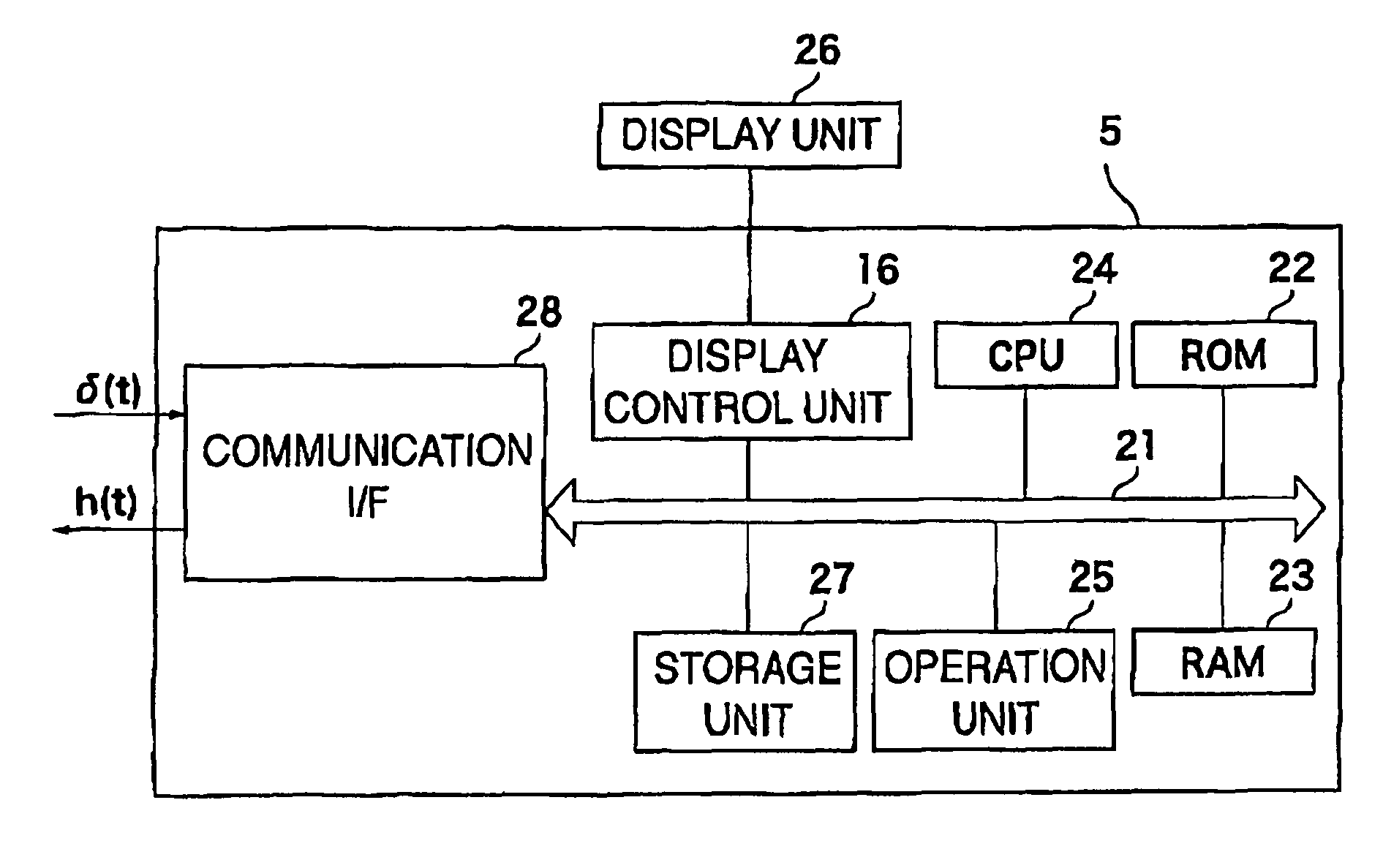
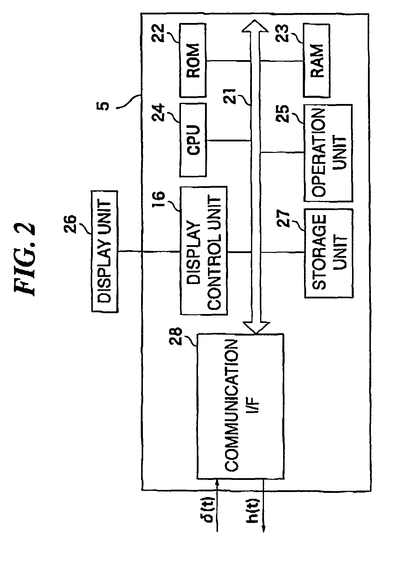
A channel characteristic analyzing apparatus that can ensure modeling of a more adequate propagation path by processing position parameters needed in a two-wave model which is used as a line-of-sight propagation path model in a stochastic manner is provided. The channel characteristic analyzing apparatus for analyzing the propagation channel characteristics of a reception apparatus 11b which has received a radio signal of a millimeter wave band, transmitted from a transmission antenna 13a of a transmission apparatus 11a, via a reception antenna 13b, includes computation means which computes h(t) expressed by the following equation (1) as a channel response to the propagation channel characteristic.h(t)=βδ(t)  (1)where β is derived as a result of processing the position parameters needed also in the two-wave model in the stochastic manner.

Description

[0001]This is a national stage of PCT / JP07 / 059636 filed May 10, 2007 and published in Japanese, which has a priority of Japanese no. 2006-308448 filed Nov. 14, 2006, hereby incorporated by reference.TECHNICAL FIELD[0002]The present invention relates to an apparatus and method for generating channel characteristics in a radio communication system using a millimeter wave band in a pseudo manner.BACKGROUND ART[0003]Recently, wide-band transmission using a millimeter wave band is attracting attention as one way of transmitting broadband signals with high quality. Particularly, radio waves of the millimeter wave band (for example, 60 GHz) have short wavelengths, leading to possible miniaturization of apparatuses, and have the physical property such that the radio waves do not reach a far distance due to their large oxygen-originated absorption attenuation, so that interference is not likely to occur. For this reason, various modes of usage as radio communication systems which realize mas...

Claims


Application Information

Patent Timeline
Patent Type & Authority Patents(United States)
IPC IPC(8): H04B1/06
CPCH04B17/3912H04B17/309
Inventor SHOJI, YOZOSAWADA, HIROKAZU
Owner NAT INST OF INFORMATION & COMM TECH
Learn More