Vessel conveying device separating a main vessel flow into a plurality of secondary flows

a conveying device and bottle type technology, applied in the direction of conveyors, mechanical conveyors, charge manipulation, etc., to achieve the effect of ensuring the reliability of the bottle transfer operation and high precision

Inactive Publication Date: 2012-11-13
SIDEL PARTICIPATIONS SAS
View PDF15 Cites 15 Cited by
  • Summary
  • Abstract
  • Description
  • Claims
  • Application Information

AI Technical Summary

Benefits of technology

[0010]The conveying system according to the invention also makes it possible to simplify the bottle circuit and ensure the reliability of this bottle transfer between the blowing machine outlet and the final conveyors. Indeed, this transfer, which is performed at high speed, induces, on the bottles, an oscillation movement associated with the centrifugation thereof, said movement tending to degrade the precision of the position of the neck of said bottles in relation to the grasping clamps and cause incidents during the transfer of said bottles.
[0019]The device according to the invention operates with clamps which are in contact with a specific portion of the bottle, i.e. the zone consisting of the neck, rim and ring situated directly below said rim. This zone of the bottle is a durable and stable portion common to a large number of bottles. It makes it possible to ensure the reliability of the bottle transfer operations, particularly for these operations for separating an initial bottle flow into a plurality of flows, said operating requiring very high precision.

Problems solved by technology

Indeed, this transfer, which is performed at high speed, induces, on the bottles, an oscillation movement associated with the centrifugation thereof, said movement tending to degrade the precision of the position of the neck of said bottles in relation to the grasping clamps and cause incidents during the transfer of said bottles.

Method used


Image

  • Vessel conveying device separating a main vessel flow into a plurality of secondary flows
  • Vessel conveying device separating a main vessel flow into a plurality of secondary flows
  • Vessel conveying device separating a main vessel flow into a plurality of secondary flows

Examples


Embodiment Construction

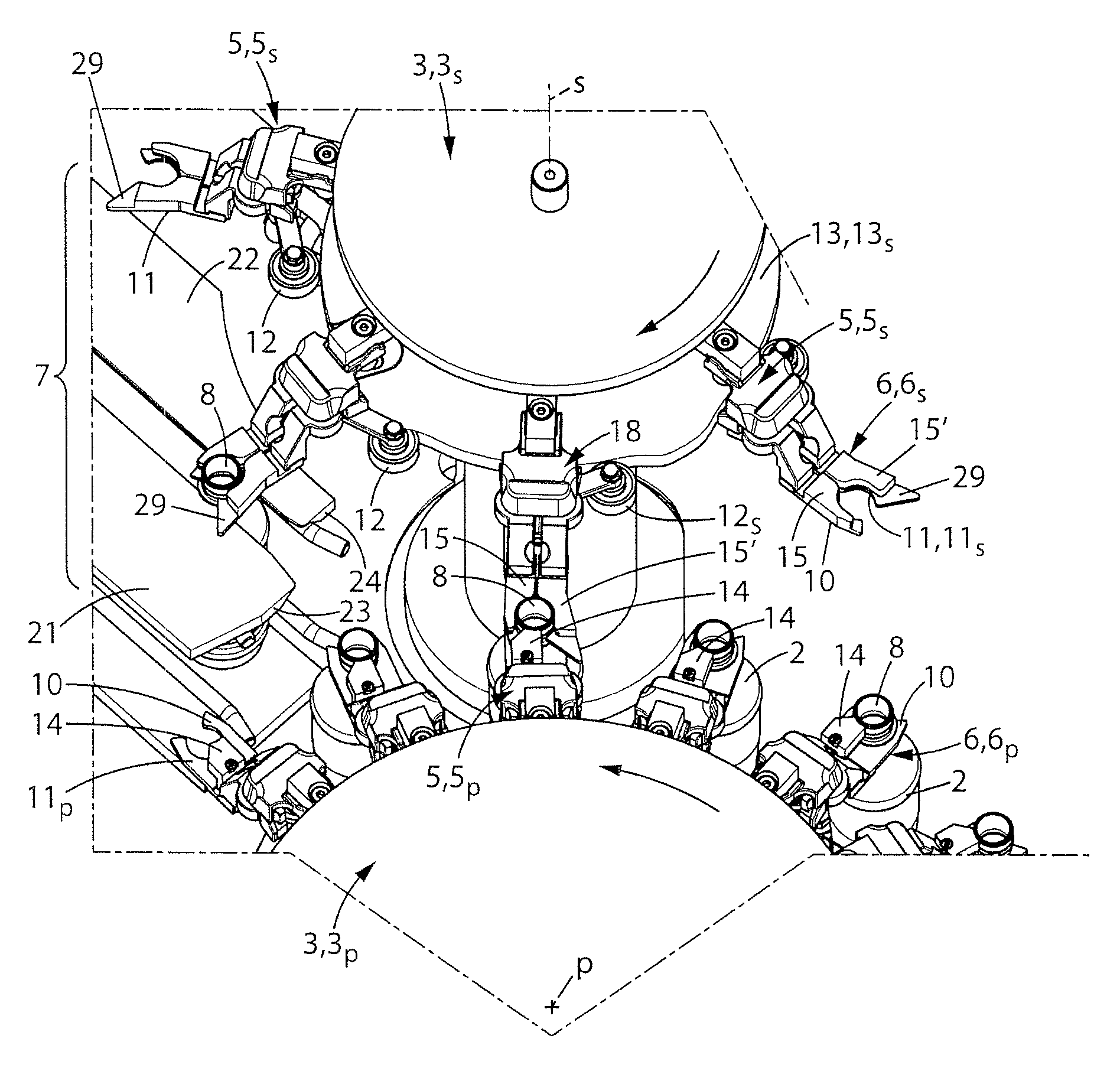
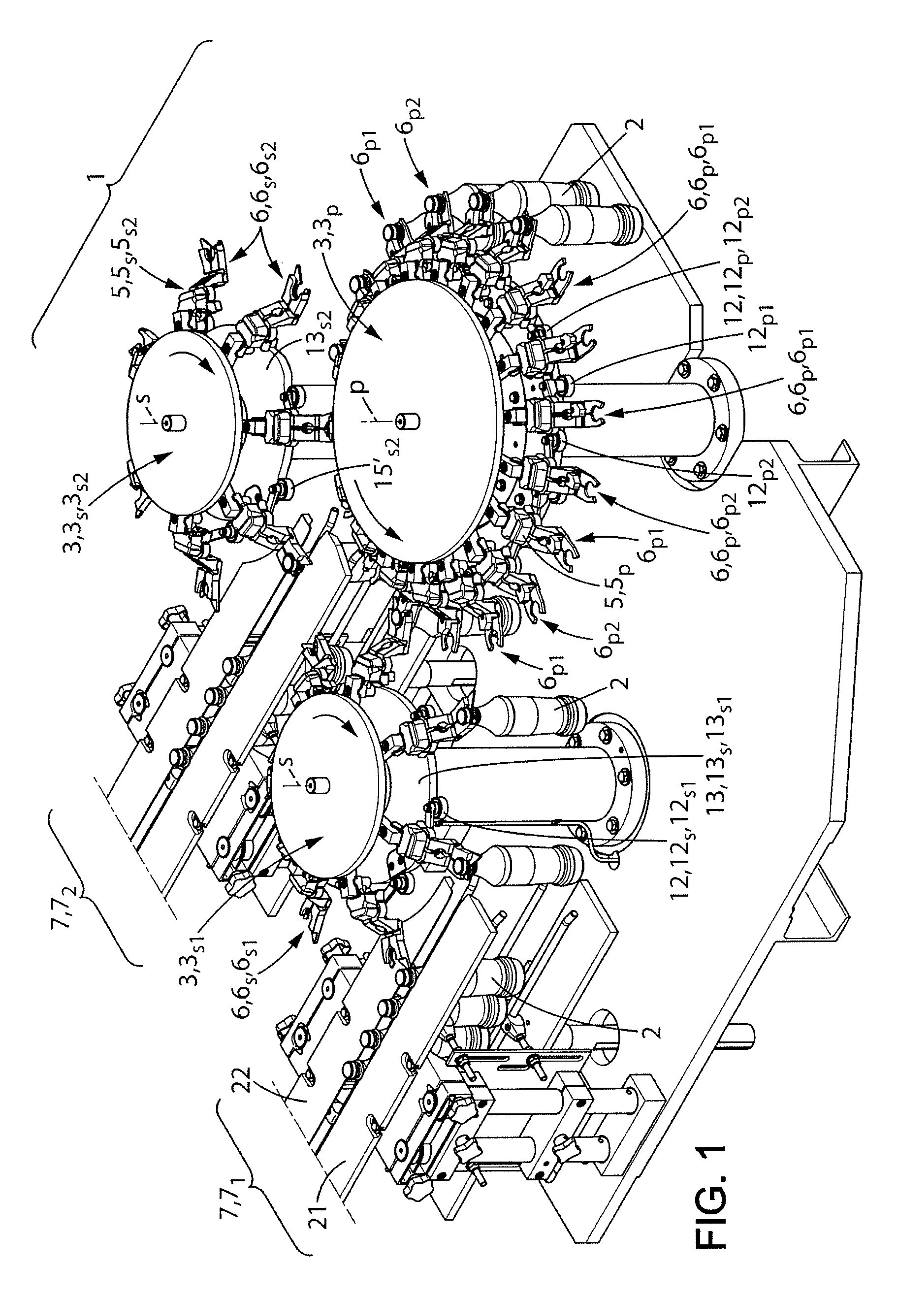
[0042]FIG. 1 represents a perspective view of a first embodiment of a device 1 for conveying and transferring vessels of the bottle type 2, said device comprising a plurality of wheels 3 rotated in a synchronised manner, similar to gears.

[0043]This device 1 comprises a first wheel hereinafter referred to as the primary conveying wheel 3p. This wheel 3p has a substantially vertical axis of rotation and is fed tangentially by a feeding member 4, represented by a single arrow, said member 4 being, for example, connected to means for unloading a blowing machine not shown. The primary wheel 3p transfers and tangentially feeds, in turn, a plurality of wheels 3 hereinafter referred to as secondary wheels 3s, always in the case of a flow separation device, as represented in FIG. 1.

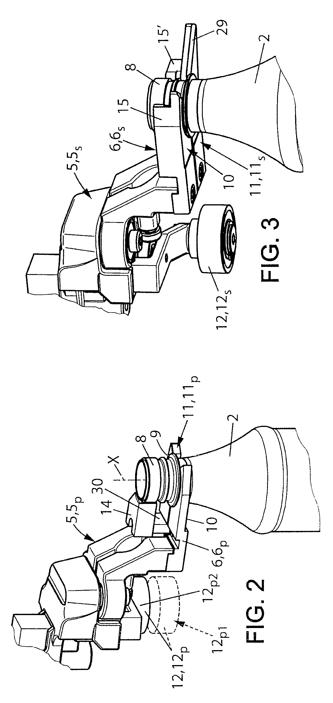
[0044]These various wheels 3 are presented, for example, in the form of a circular plate at the periphery whereof arms 5 are attached at regular intervals in a star pattern. They are rotated, in a synchronised man...


PUM


Abstract

The invention relates to a device for conveying vessels of the bottle type, characterized in that it comprises: a primary wheel for conveying the bottles including a plurality of transfer arms; at least two secondary conveying wheels respectively capable of conveying the bottles fed by the primary wheel; the conveying path of the bottles grasped by the clamps of the transfer arms of each secondary wheel being at one point tangential to the conveying path of the bottles grasped by the transfer arms of the primary wheel, whereby the main flow of bottles conveyed by the primary wheel is divided into at least two secondary flows of bottles respectively conveyed by the secondary conveying wheels.

Description

FIELD OF THE DESCRIPTION[0001]The present invention relates to a device for conveying vessels of the bottle type, for separating a main vessel flow, fed at the outlet of an upstream vessel processing machine, into a plurality of secondary vessel flows respectively intended for a plurality of machines located downstream.[0002]The invention more specifically applies to the conveying of blown vessels, such as bottles, at the outlet of a circular blowing conveyor consisting of a plurality of blowing stations arranged at the periphery thereof.[0003]After the blowing operation at the outlet of the circular blowing conveyor, the blown bottles must be conveyed to other processing machines such as, for example, filling machines or palletisers for the transport thereof to another site.DESCRIPTION OF THE PRIOR ART[0004]In view of the production rates of blowing machines, it is necessary to separate the flow at the outlet of such a machine to, in particular, prevent bottle jamming problems in t...

Claims


Application Information

Patent Timeline
Patent Type & Authority Patents(United States)
IPC IPC(8): B65G47/84
CPCB65G47/71B65G47/847B65G2201/0247
Inventor NGUYEN, DANIELMORIN, STEPHANELANGLOIS, PIERRE-FRANCOIS
Owner SIDEL PARTICIPATIONS SAS
Why Eureka
Try Eureka