
Electronic measuring wheel

a technology of electronic measuring wheel and glass cover, which is applied in the direction of measuring wheels, mechanical measuring arrangements, instruments, etc., can solve the problems of inconvenient use, inability to see the measurement data on the glass cover easily under bright lighting, and inability to meet the needs of users, etc., and achieves the effect of high brightness

Active Publication Date: 2012-11-13
WANG CHENG LIN
View PDF8 Cites 8 Cited by
  • Summary
  • Abstract
  • Description
  • Claims
  • Application Information

AI Technical Summary

Benefits of technology

"The present invention provides an electronic measuring wheel with high brightness and durability. It includes a casing with a display and sensor, a distance wheel with an axle and induction ring, and an operating shaft. The distance wheel is connected to the casing and can rotate to measure distances. The technical effects of this invention include improved accuracy and reliability in measuring distances, as well as improved durability and reliability of the electronic measuring wheel."

Problems solved by technology

However, the glass cover of the liquid crystal display (55) may easily be broken and the measurement data on the glass cover cannot be seen easily under bright lighting, such as under sunshine.
To clearly see the measurement data on the glass cover of the liquid crystal display (55), the liquid crystal display (55) has to be shaded so is inconvenient to use.
Furthermore, when the liquid crystal display (55) is exposed to water, water may flow under the glass cover and into the liquid crystal display (55) causing short circuit and breakage or obscuring the display (55).
Therefore, the glass cover of the liquid crystal display (55) cannot provide a waterproof effect and this will increase the cost of using the conventional electric range finder (50).

Method used


Image

  • Electronic measuring wheel
  • Electronic measuring wheel
  • Electronic measuring wheel

Examples


Embodiment Construction

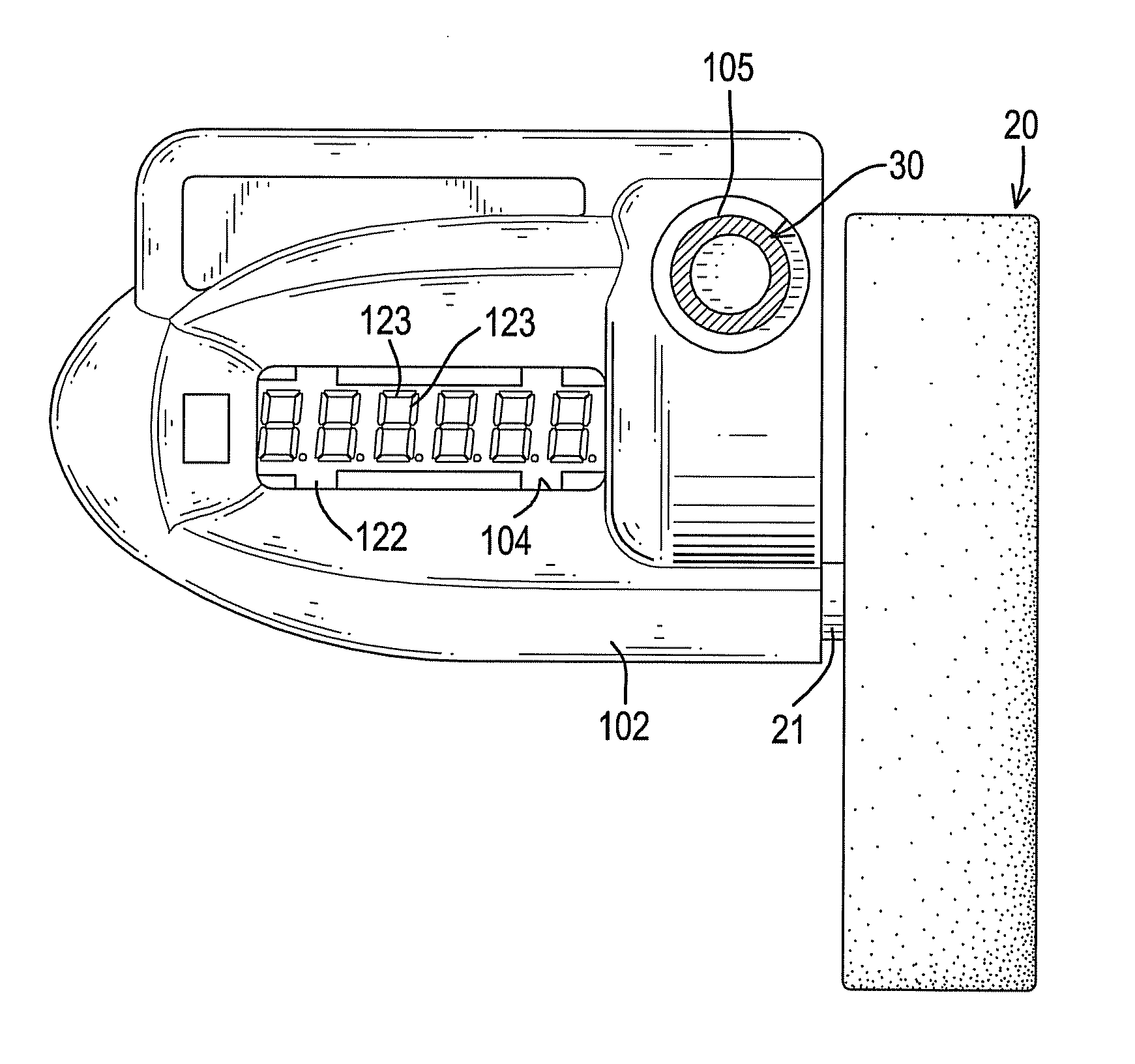
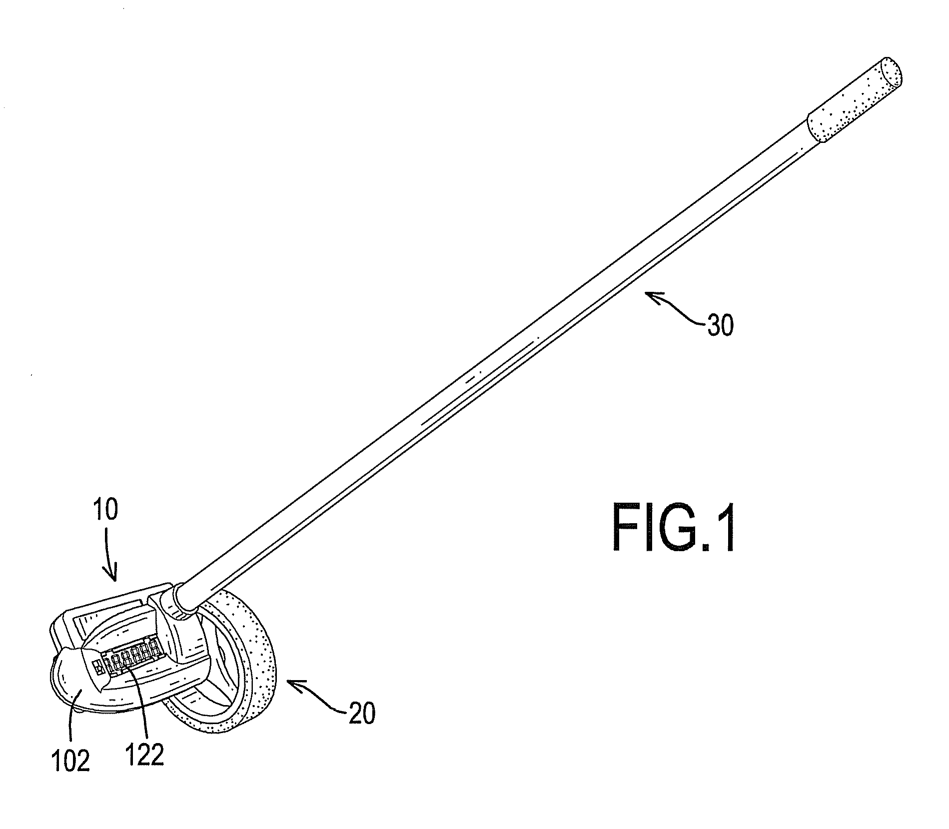
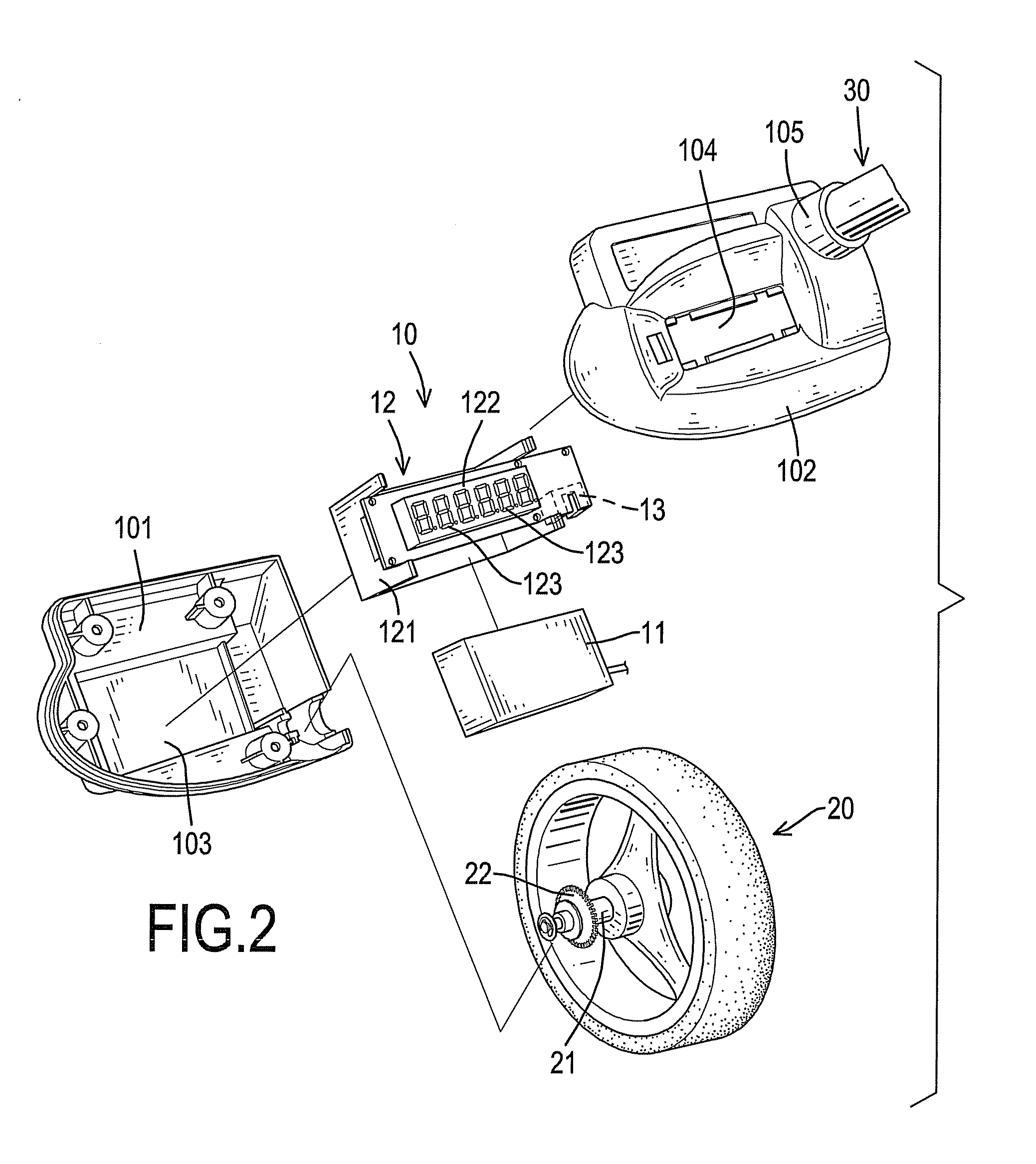
[0014]With reference to FIGS. 1, 2 and 3, an electronic measuring wheel in accordance with the present invention has a casing (10), a distance wheel (20) and an operating shaft (30).

[0015]The casing (10) may be composed of two half-casings (101, 102) and has a power supply (11), a seven-segment display (12) and a sensor (13). The half-casings (101, 102) are combined with each other and have a lower half-casing (101) and an upper half-casing (102). The lower half-casing (101) has a mounting recess (103). The upper half-casing (102) is detachably combined with the lower half-casing (101) and has a top surface, a window (104) and a mounting tube (105). The window (104) is formed through the top surface of the upper half-casing (102) and communicates with the mounting recess (103) of the lower half-casing (101). The mounting tube (105) is formed on and protrudes from the top surface of the upper half-casing (102).

[0016]The power supply (11) is mounted in the casing (10) and may be a bat...


PUM


Abstract

An electronic measuring wheel has a casing, a distance wheel and an operating shaft. The casing has a power supply, a seven-segment display and a sensor. The seven-segment display is mounted in the casing and is electrically connected to the power supply. The sensor is mounted on the seven-segment display in the casing and is electrically connected to the power supply and the seven-segment display. The distance wheel is rotatably connected to the casing and has a distance wheel axle and an induction ring. The distance wheel axle has an inner end mounted in the casing. The induction ring is mounted around the inner end of the distance wheel axle near the sensor. The operating shaft is connected to the casing.

Description

BACKGROUND OF THE INVENTION[0001]1. Field of the Invention[0002]The present invention relates to an electronic measuring wheel, and more particularly relates to an electronic measuring wheel that can provide a high brightness and a breakage-proof effect.[0003]2. Description of Related Art[0004]With reference to FIG. 4, a conventional electronic measuring wheel (50) is used to measure a distance between two objects and has a casing (51), a distance wheel (52) and an operating shaft (53). The casing (51) has a chamber, a top surface, a window, a sensor (54), a liquid crystal display (55) and a power supply (56). The window is formed in the top surface of the casing (51) and communicates with the chamber of the casing (51). The sensor (54) is mounted in the chamber of the casing (51). The liquid crystal display (55) is mounted in the casing (51) near the window and is electrically connected to the sensor (54). The power supply (56) is mounted in the chamber of the casing (51) near the ...

Claims


Application Information

Patent Timeline
Patent Type & Authority Patents(United States)
IPC IPC(8): G01B7/04G01B7/30G01B5/00
CPCG01B3/12
Inventor LAI, YING-WU
Owner WANG CHENG LIN
Learn More