
Mixers for a viscometer and methods for using the same

a technology of viscometer and mixer, which is applied in the direction of process and machine control, instruments, transportation and packaging, etc., can solve the problems of printing press fouled, adversely affecting modern industrial equipment, and affecting print quality

Inactive Publication Date: 2012-11-20
SAINT CLAIR SYST INC
View PDF11 Cites 2 Cited by
  • Summary
  • Abstract
  • Description
  • Claims
  • Application Information

AI Technical Summary

Benefits of technology

The system effectively mixes liquids at low fluid levels without introducing air, providing accurate viscosity control and preventing equipment fouling, thus improving print quality and extending equipment lifespan.

Problems solved by technology

Perhaps more importantly, an inappropriate viscosity can adversely affect modern industrial equipment.
For example, if the viscosity of printing ink falls outside of an acceptable viscosity ranges, not only is print quality affected, but the printing press can also become fouled.
Such additions will not immediately integrate the mixture, and therefore neither effect the desired viscosity adjustment nor allow the user to determine with a viscometer whether the adjustment was sufficient to produce the desired viscosity.
These mixers suffer from a variety of drawbacks.
First, conventional mixers can cost approximately $500.
Second, many conventional mixers incorporate a significant amount of air into the mixture, especially where the fluid level in the vessel is low.
In addition to distorting a viscosity measurement, this air can degrade processes such a printing.

Method used


Image

  • Mixers for a viscometer and methods for using the same
  • Mixers for a viscometer and methods for using the same
  • Mixers for a viscometer and methods for using the same

Examples


Embodiment Construction

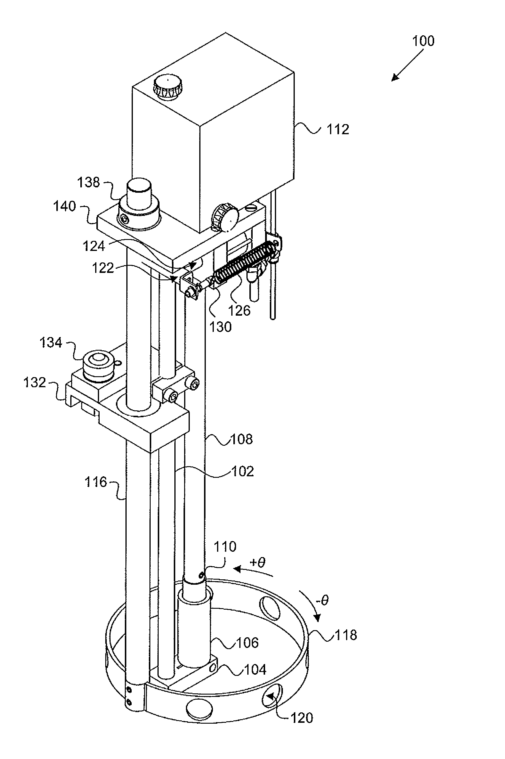
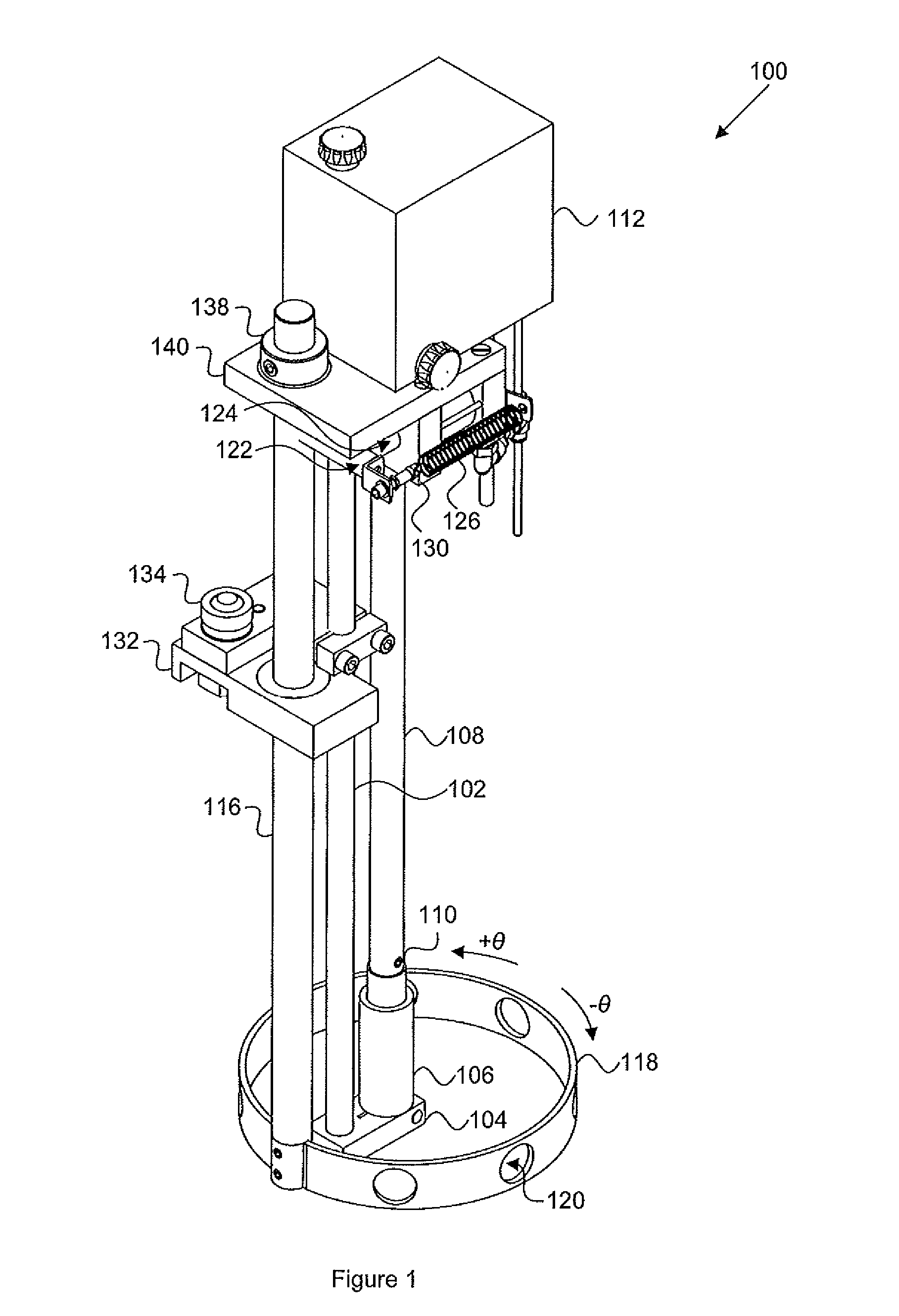
[0018]The present invention relates to a mixer for incorporation with a viscometer. Referring to FIG. 1, a viscosity control system 100 is provided. Viscosity control system 100 includes a viscometer. The viscometer can be any of a variety of known viscometers including falling piston, falling sphere, vibrational viscometers, rotation viscometers, Stabinger viscometers, and Stormer viscometers. Viscometers are available from a variety of sources including, for example, Norcross Corporation of Newton, Mass.

[0019]The embodiment depicted in FIG. 1 includes a failing piston viscometer. The falling piston viscometer includes a supporting shaft 102 connected to bracket 104 for supporting tube 106. Lifter cylinder 108 periodically lifted, thereby lifting piston 110. After piston 110 is raised so that tube 106 fills with the liquid to be measured, lifter cylinder 108 and piston 110 are released, allowing piston 110 to fall by force of gravity and displace fluid in tube 106. The piston 110, ...


PUM


Abstract

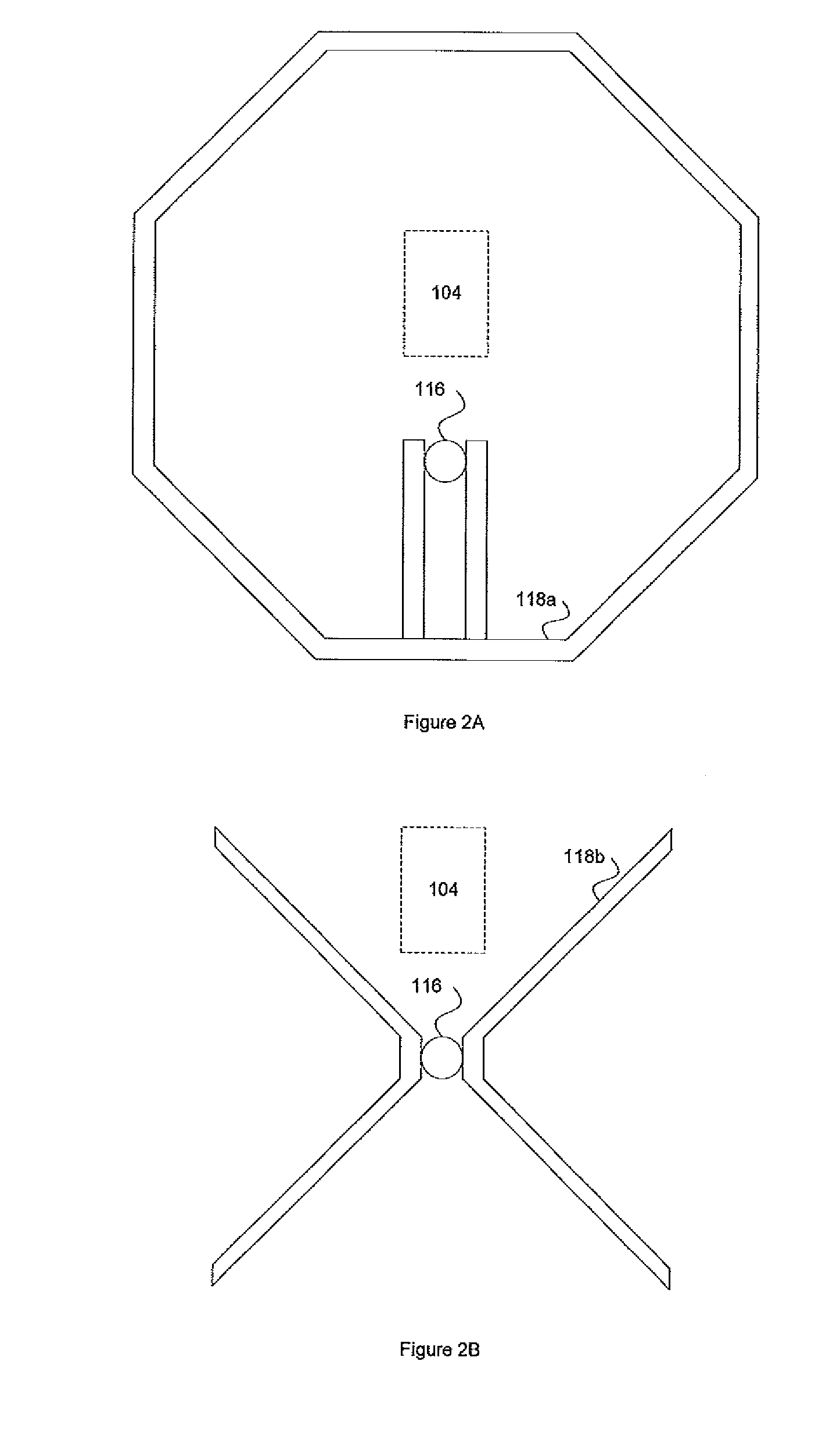
The present invention is directed to mixers for viscometers and methods of using the same. Such inventions are applicable, for example, to industrial processes such as printing. One embodiment of the invention is directed to a viscosity control system including a viscosity sensor, a mixing element, a shaft fixedly attached to the mixing element, and an actuator interfacing with the viscosity sensor and the shaft. The annular mixing element is oscillatable about an axis lying in a plane tangent to a point on a wall of the mixing element. The shaft is centered about the axis. The actuator receives a signal from the viscosity sensor and rotates the shaft and the mixing element in an oscillating manner about the axis. In some embodiments, the shaft rotates through an angle of less than 360 degrees.

Description

RELATED APPLICATIONS[0001]This application is a continuation under 35 U.S.C. §120 of International Application No. PCT / US2010 / 028467, filed Mar. 24, 2010, which claims priority to U.S. Provisional Patent Application Ser. No. 61 / 162,802, filed Mar. 24, 2009. The entire contents of each of these applications are hereby incorporated by reference herein.FIELD OF INVENTION[0002]The present invention is directed to mixers for viscometers and methods of using the same. Such inventions are applicable, for example, to industrial processes such as printing.BACKGROUND[0003]Viscosity control is essential in many of today's manufacturing and printing processes. Viscosity is the measure of the resistance of a fluid to deformation by either shear stress or extensional stress, but is commonly perceived as the “thickness” or resistance to flow of a fluid. Viscosity can be an important quality of a finished product (e.g. a lubricant, paint, or ink) or can affect a finished product (e.g. printed mater...

Claims


Application Information

Patent Timeline
Patent Type & Authority Patents(United States)
IPC IPC(8): B01F11/00B01F25/60
CPCB01F11/0088B01F11/0091B01F15/00207B01F15/00246G01N11/00G05D24/02G01N2011/0046B01F31/445B01F31/449B01F35/2136B01F35/213
Inventor NORCROSS, JR., ROBERT A.
Owner SAINT CLAIR SYST INC
Learn More