Structure of electromagnetic wave resistant connector for flexible circuit cable

a technology of flexible circuit cables and connectors, which is applied in the direction of electrical equipment, printed circuits, coupling device connections, etc., can solve the problems of improper and unstable insertion, reduced thickness and flexibility, and not constructed for protection against electromagnetic waves, so as to achieve the effect of enhancing resistance against electromagnetic waves

Active Publication Date: 2012-11-20
ADVANCED FLEXIBLE CIRCUITS
View PDF5 Cites 6 Cited by
  • Summary
  • Abstract
  • Description
  • Claims
  • Application Information

AI Technical Summary

Benefits of technology

[0007]Thus, an objective of the present invention is to provide a structure of electromagnetic wave resistant connector for flexible flat cable, wherein an insertion device is coupled to a flexible flat cable to ensure insertion stability and also to provide protection against electromagnetic wave.
[0009]To achieve the above objectives, according to the present invention, a flexible flat cable forms an insertion device mounting section to which an insertion device is mounted. The insertion device comprises a metal member that is at least partly formed of a metal material. The flexible flat cable forms the conductive traces on which an insulation layer is provided. The insulation layer has a surface, which forms, in at least a portion thereof, a conductive shielding layer that is electrically connectable to a grounding path. The conductive shielding layer extends to the insertion device mounting section, so as to provide electromagnetic wave protection with the metal member of the insertion device and the conductive shielding layer when the insertion device is mounted to the insertion device mounting section, and thereby meet the needs for enhanced resistance against electromagnetic waves for electronic devices. Further, through the flexible flat cable connector structure that is thickness adjustable, the present invention can provide diverse thicknesses of insertion device to match different sizes of a corresponding insertion slot.

Problems solved by technology

A flexible flat cable is characterized by reduced thickness and flexibility, and this often leads to improper and unstable insertion when the flexible flat cable is inserted into a mating connection slot.
Although this known structure of insertion device helps improving the engagement stability of the insertion device in an insertion operation, it is not constructed for protection against electromagnetic wave.
It leads to an insufficiency of electromagnetic wave protection of the flexible flat cable at the section where the insertion device is mounted.
Further, although the known insertion device is adopted to overcome the problems of improper and unstable insertion, the known insertion device does not provide sufficient mechanical stability for the front end portion thereof.

Method used


Image

  • Structure of electromagnetic wave resistant connector for flexible circuit cable
  • Structure of electromagnetic wave resistant connector for flexible circuit cable
  • Structure of electromagnetic wave resistant connector for flexible circuit cable

Examples


first embodiment

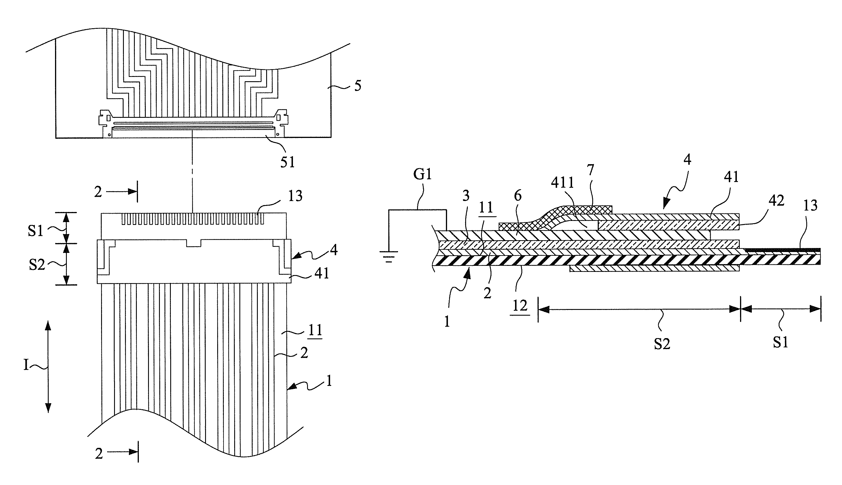
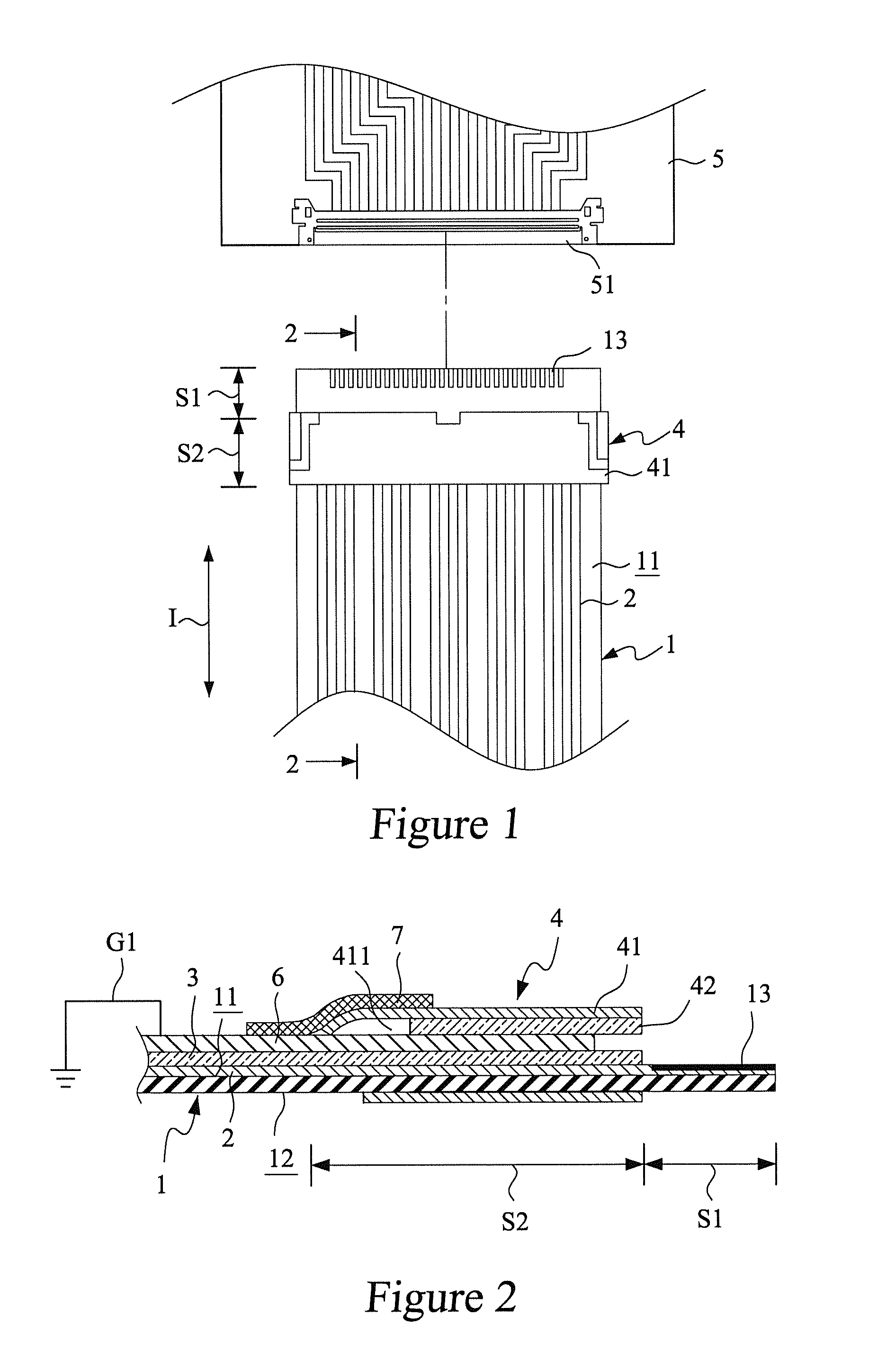
[0018]With reference to the drawings and in particular to FIGS. 1 and 2, which show a schematic view and a cross-sectional of a first embodiment according to the present invention, a flexible flat cable 1 has a first surface 11 and a second surface 12. The flexible flat cable 1 extends in a cable extension direction I so that the flexible flat cable 1 forms an insertion section S1 at a free end thereof and also forms an insertion device mounting section S2 in a section thereof adjacent to the insertion section S1.

[0019]The first surface 11 of the flexible flat cable 1 forms a plurality of parallel and spaced conductive traces 2. The conductive traces 2 extend through the insertion device mounting section S2 into the insertion section S1 of the flexible flat cable 1 to form a plurality of conductive contacts 13 in the insertion section S1.

[0020]An insulation layer 3 is provided on the first surface 11 of the flexible flat cable 1 and surfaces of the conductive traces 2. An insertion ...

second embodiment

[0025]Referring to FIG. 6, a cross-sectional view of a second embodiment according to the present invention is shown. In the instant embodiment, part / components that are similar or identical to counterparts of the previous embodiment bear the same reference for consistency and simplification. In the instant embodiment, a mechanical reinforcement layer 8 made of insulation material is provided on the second surface 12 of the flexible flat cable 1 to cover both the insertion section S1 and the insertion device mounting section S2. The mechanical reinforcement layer 8 helps improving the mechanical strengths of the insertion section S1 and the insertion device mounting section S2 of the flexible flat cable 1 to ensure stable insertion of the flexible flat cable 1 into the insertion slot 51 of the circuit board 5.

third embodiment

[0026]Referring to FIG. 7, a cross-sectional view of a third embodiment according to the present invention is shown. In the instant embodiment, a shielding layer 9 made of a conductive material is provided on the second surface 12 of the flexible flat cable 1 to cover both the insertion section S1 and the insertion device mounting section S2. The shielding layer 9 is in electrical engagement with the metal member 41 of the insertion device 4 and the shielding layer 9 is electrically connectable to a second grounding path G2. The second grounding path G2 and the first grounding path G1 may be connected to each other through a via or by a conductive material extending between both surfaces to thereby form a common ground.


PUM


Abstract

Disclosed is a structure of electromagnetic wave resistant connector for flexible flat cable. A flexible flat cable defines an insertion device mounting section to which an insertion device is mounted. The insertion device includes a metal member that is at least partly formed of a metal material. The flexible flat cable forms thereon conductive traces on which an insulation layer is provided. The insulation layer has a surface, which forms, in at least a portion thereof, a conductive shielding layer. The conductive shielding layer extends to the insertion device mounting section, so that when the insertion device is mounted to the insertion device mounting section, electrical connection is formed between the metal member of the insertion device and the conductive shielding layer.

Description

FIELD OF THE INVENTION[0001]The present invention relates to an insertion and connection structure for flexible flat cables, and in particular to a structure of electromagnetic wave resistant connector for flexible flat cable.BACKGROUND OF THE INVENTION[0002]Flexible flat cables are widely used in various electronic products, such as notebook computers, personal digital assistants, and mobile phones. A conventional flexible flat cable comprises a plurality of conductors that are each enclosed by an insulation layer and are arranged to juxtapose each other to form a flat structure. A connector or soldering is provided on the flat cable for transmission of electronic signals.[0003]A flexible flat cable is characterized by reduced thickness and flexibility, and this often leads to improper and unstable insertion when the flexible flat cable is inserted into a mating connection slot. To overcome such a problem, it is often to add an insertion device at a leading end of the flexible flat...

Claims


Application Information

Patent Timeline
Patent Type & Authority Patents(United States)
CPCH01R12/775H01R13/025
Inventor LIN, GWUN-JINSU, KUO-FUCHUO, CHIH-HENG
Owner ADVANCED FLEXIBLE CIRCUITS
Why Eureka
Try Eureka