Multi-level spinal stabilization system

a spinal stabilization system and multi-level technology, applied in the field of advantages, can solve the problems of 4.5 million people, compromise postoperative function, and sufferers of low back pain that fail conservative therapy, and achieve the effects of superior clinical results, convenient installation, and versatility/flexibility in application

Active Publication Date: 2012-11-20
RACHIOTEK
View PDF94 Cites 50 Cited by
  • Summary
  • Abstract
  • Description
  • Claims
  • Application Information

AI Technical Summary

Benefits of technology

[0009]According to the present disclosure, advantageous devices, systems and methods for spinal stabilization are provided. According to preferred embodiments, the disclosed devices, systems and methods provide dynamic stabilization to the spine so as to provide clinically efficacious results. In addition, the disclosed devices, systems and methods offer clinical advantages, including ease of installation, versatility / flexibility in application, and superior clinical results for individuals encountering lower back pain and other spine-related difficulties.
[0020]The elongated members / spinal support rods disclosed herein allow for extra rotational degrees of freedom by virtue of the enlarged, ball-like heads when used in combination with the rotating ball and socket joint of the intermediate connector.
[0021]The multi-level dynamic spinal stabilization system disclosed herein allows for superior sacral to lumbar vertebral spanning by virtue of the specially designed inferior vertebral connectors / rods and multi-angle orientation utility of the inferior vertebral connector and the intermediate connector, as well as for superior vertebral spanning across two levels.

Problems solved by technology

However, approximately 15 percent, or 4.5 million, low back pain sufferers fail conservative therapy and are left with debilitating pain.
However, the by-products of this surgical procedure and preparation for fusion are damage of the posterior muscles and loss of intervertebral motion which can compromise postoperative function and place abnormal stresses on the adjacent spine levels.
Further, the S-1 pedicle, made up for five fused vertebrae below the lumbar region, is larger than the lumbar pedicles, having Sacral Ala or “wings”, and presents unique anatomical problems in spinal stabilization methodologies.

Method used


Image

  • Multi-level spinal stabilization system
  • Multi-level spinal stabilization system
  • Multi-level spinal stabilization system

Examples


Embodiment Construction

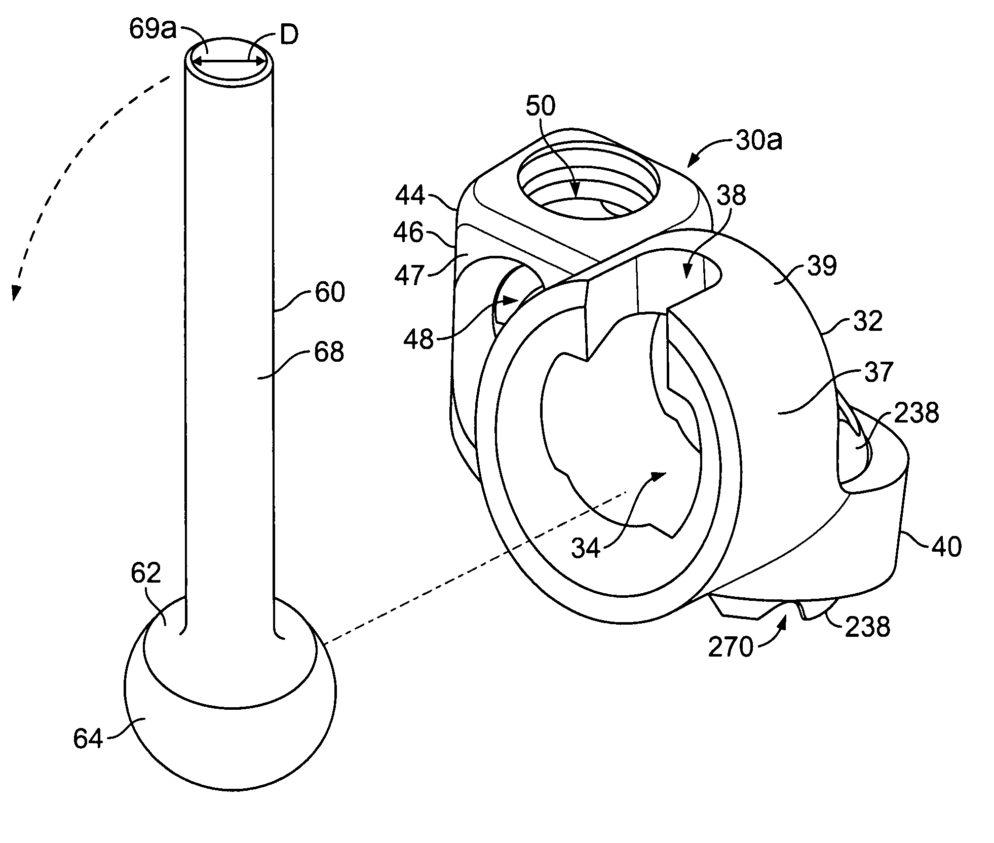
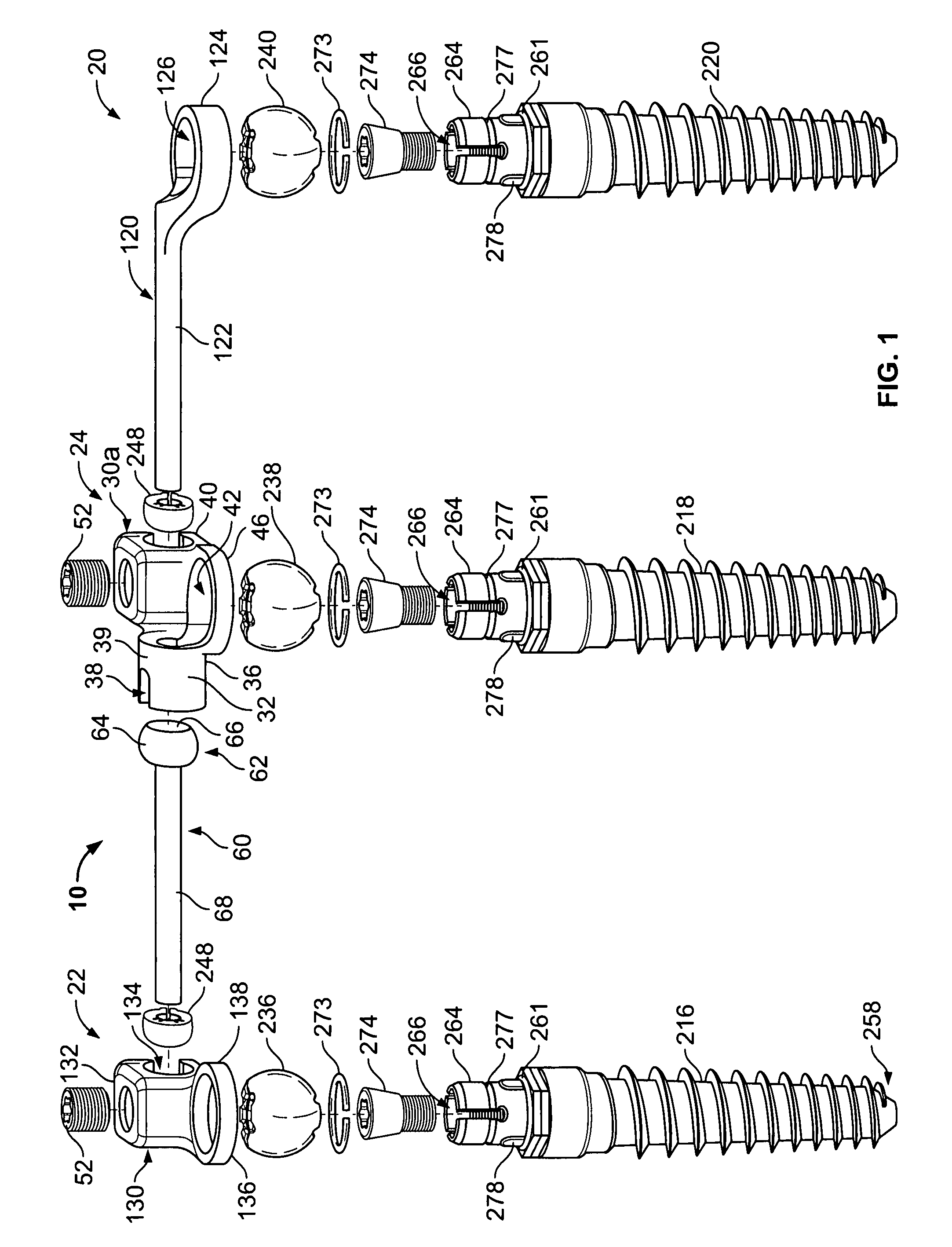
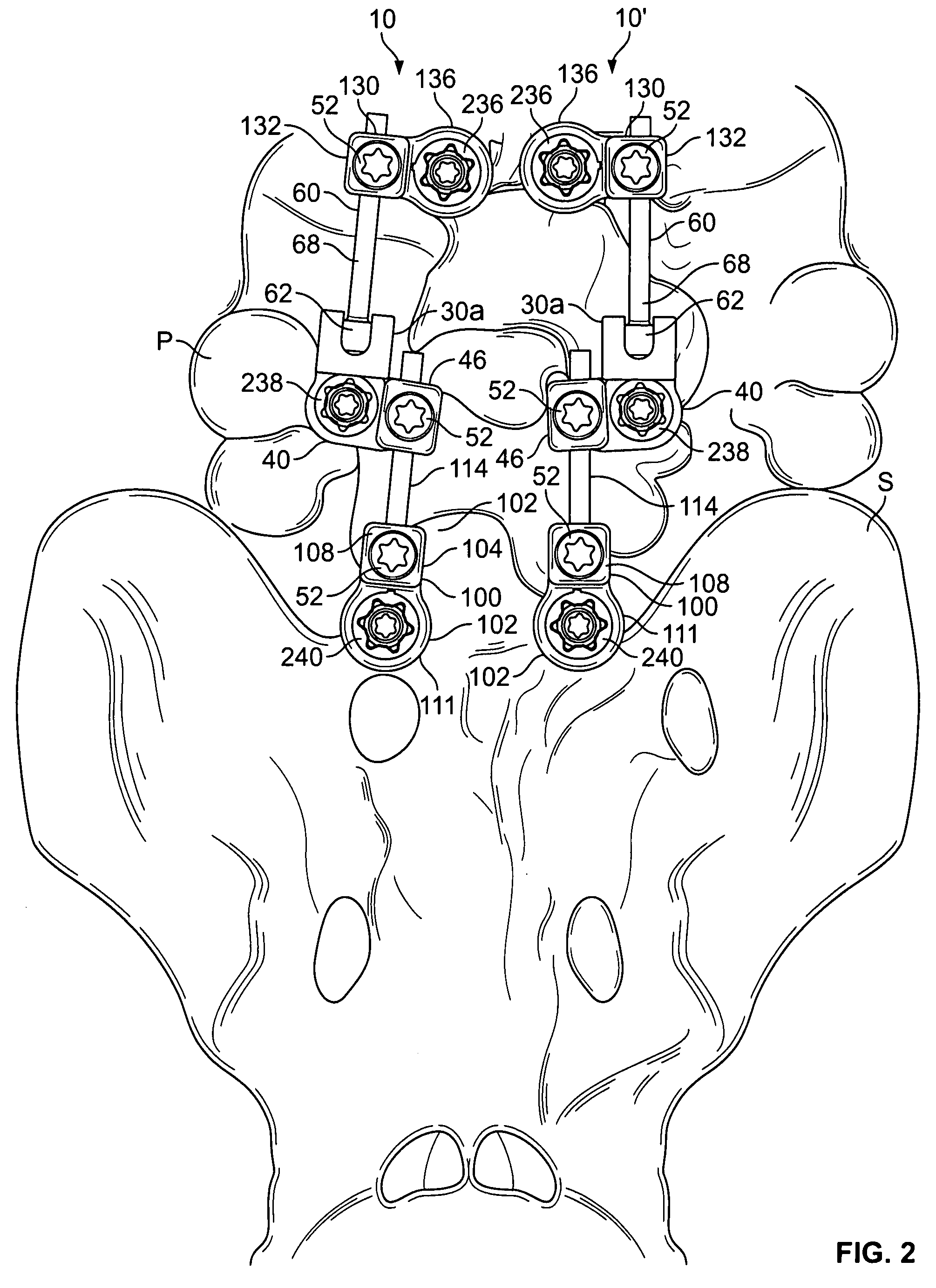
[0059]The present disclosure provides advantageous devices, systems and methods for providing dynamic spinal stabilization. More particularly, the present disclosure provides a multi-level dynamic spinal stabilization system with a multi-level intermediate connector configured for attachment of an elongated member in a dynamic ball and socket junction and including a second attachment member for reception of an elongated member extending from an inferior end connector at a variable orientation with respect to other elongated members of the system.

[0060]The exemplary embodiments disclosed herein are illustrative of the advantageous spinal stabilization devices / systems and surgical implants of the present disclosure, and of methods / techniques for implementation thereof. It should be understood, however, that the disclosed embodiments are merely exemplary of the present invention, which may be embodied in various forms. Therefore, the details disclosed herein with reference to exemplar...


PUM


Abstract

Multi-level spinal stabilization devices, systems and methods are provided that include at least one multi-level connector, one elongated member with an enlarged head, at least one pedicle screw, and at least one mechanism that supports three degrees of rotational freedom relative to both the elongated member and the pedicle screw each. The mechanism may include universal joint mechanisms or ball and socket mechanisms. In the case of the ball and socket mechanisms, the enlarged head of the elongated member cooperates with a first socket member of the multi-level connector to define a dynamic junction that allows the socket member to move relative to the enlarged head of the elongated member while remaining engaged therewith.

Description

BACKGROUND OF THE INVENTION[0001]1. Technical Field[0002]The present disclosure relates to advantageous methods and apparatus for spinal stabilization. More particularly, the present disclosure relates to devices, systems and methods for providing dynamic stabilization to the spine via the use of an intermediate multi-level connector for dynamic attachment of elongated members spanning one or more spinal levels at multi-level orientations.[0003]2. Background Art[0004]Back pain is most frequently associated with degenerative or traumatic changes in the lumbar vertebrae and / or disks. The vast majority of the 30 million U.S. patients who report back pain each year resolve their pain with conservative treatment or, simply, rest and exercise. However, approximately 15 percent, or 4.5 million, low back pain sufferers fail conservative therapy and are left with debilitating pain. Of these, some 500,000 opt for surgery.[0005]In addition to alleviating pain, spine surgery seeks to minimize d...

Claims


Application Information

Patent Timeline
Patent Type & Authority Patents(United States)
IPC IPC(8): A61B17/70
CPCA61B17/7005A61B17/7035A61B17/704A61B17/7041
Inventor BRENNAN, TERRENCEMALCOLMSON, GEORGE F.WALTERS, CARMENZLOCK, STEPHEN W.TIMM, JENS PETER
Owner RACHIOTEK
Why Eureka
Try Eureka