Layer opacity adjustment for a three-dimensional object

a three-dimensional object and layer opacity technology, applied in the field of visualizing three-dimensional objects using a, can solve the problems of difficult to locate distinct features or visualize distinct layers, and difficult to adjust the opacity of layers and features of 3d objects, and achieve the effect of reducing the opacity of at least one of the plurality of layers that is passed through

Active Publication Date: 2012-11-20
GOOGLE LLC
View PDF13 Cites 42 Cited by
  • Summary
  • Abstract
  • Description
  • Claims
  • Application Information

AI Technical Summary

Benefits of technology

[0009]In certain embodiments of the system, the processor is further configured to provide data for another view of the 3D object in response to a request from a user, wherein a transition from the view of the 3D object to the other view of the 3D object includes the processor being configured to adjust an opacity of at least one of the plurality of layers of the 3D object based on the transition. In certain embodiments of the system, the processor is further configured to provide data for another view of the 3D object in response to a request from a user, wherein a transition from the view of the 3D object to the other view of the 3D object includes passing through at least one of the plurality of layers of the 3D object. In certain embodiments of the system, during the transition from the view of the 3D object to the other view of the 3D object, an opacity of the at least one of the plurality of layers that is passed through is decreased. In certain embodiments of the system, the processor is further configured to retrieve from storage and display within the view of the 3D object at least one identification label associated with at least one portion of the 3D objection within the view based on input received from the user. In certain embodiments of the system, the processor is further configured to provide data for another view of the 3D object in response to a request from a user, wherein the position and the opacity of the identification label within the other view is adjusted based on the position of the other view of the 3D object. In certain embodiments of the system, the layer of the 3D object that is both within the view and furthest from the view remains substantially opaque, and wherein another layer outside of the view becomes substantially transparent. In certain embodiments of the system, the processor is further configured to generate, for display, a layer opacity adjustment interface for the 3D object, the interface includes at least one slide indicator, receive a request to move a position of the slide indicator, and adjust an opacity level of at least one of the layers of the 3D object based on the position movement of the slide indicator. In certain embodiments of the system, the slide indicator is a vertical slide indicator configured to move along a first axis, and the position of the vertical slide indicator along the first axis is configured to affect the opacity of each of the layers of the 3D object. In certain embodiments of the system, the adjustment interface includes a layer indicator for each layer displayed along the first axis, and movement of the vertical slide indicator across a layer indicator includes an adjustment of an opacity level of the layer indicated by the layer indicator. In certain embodiments of the system, the opacity adjustment interface further includes a horizontal slide indicator for each layer indicator, each horizontal slide indicator is configured to move across the layer indicator along a second axis that is different than the first axis, movement of each horizontal slide indicator across a layer indicator along the second axis includes an adjustment of an opacity level of the layer indicated by the layer indicator, and the position of each horizontal slide indicator is limited to affecting the opacity of the corresponding layer with which the horizontal slide indicator is associated.

Problems solved by technology

However, these conventional systems typically require the installation of specialized software in order to permit the 3D object to be displayed in the 3D space.
Furthermore, if the 3D object has many distinct features and / or layers, it may be very difficult to locate the distinct features or visualize the distinct layers, let alone locate distinct features on each distinct layer of the 3D object.
For example, it is difficult to adjust the opacity of the layers and features of the 3D object in order to easily view a portion of the 3D object.

Method used


Image

  • Layer opacity adjustment for a three-dimensional object
  • Layer opacity adjustment for a three-dimensional object
  • Layer opacity adjustment for a three-dimensional object

Examples


Embodiment Construction

[0023]In the following detailed description, numerous specific details are set forth to provide a full understanding of the present disclosure. It will be apparent, however, to one ordinarily skilled in the art that the embodiments of the present disclosure may be practiced without some of these specific details. In other instances, well-known structures and techniques have not been shown in detail so as not to obscure the disclosure.

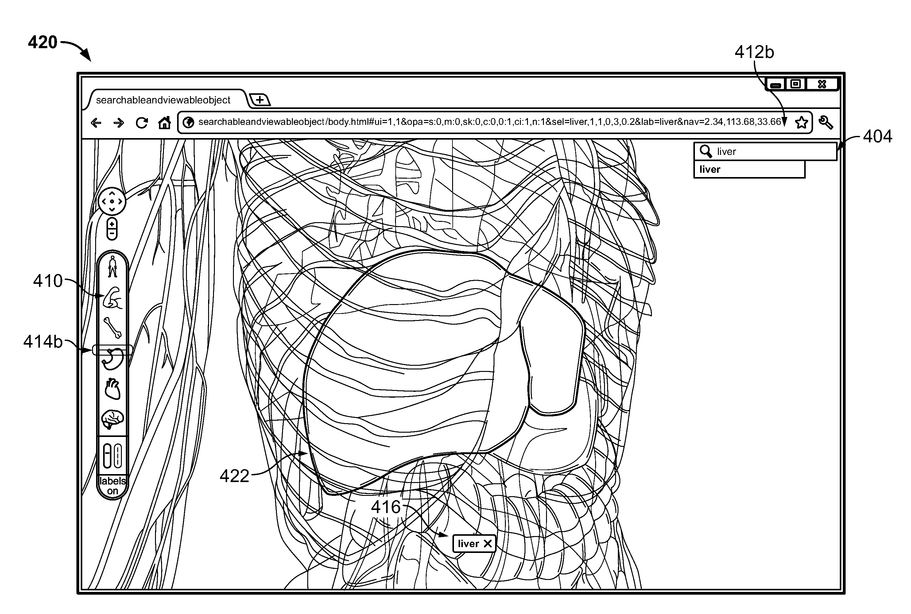
[0024]The disclosed system uses a web browser with integrated (e.g., built in) 3D modeling and searching capabilities for viewing and searching a 3D image or object, such as a web browser pre-installed with WebGL. Using the enhanced web browser, the user can view, search and transcend layers of the 3D image, each view having a separate Uniform Resource Locator (URL). For example, a user viewing a 3D model of the human body can start from an external view of the liver and transcend, layer by layer, through the liver in order to view a bile duct, with eac...


PUM


Abstract

Computer-implemented methods for automatically adjusting an opacity of layers in a three-dimensional (3D) object are provided. In one aspect, a method includes receiving a request to display data for a 3D object having a plurality of layers, and providing, for display, data for a view of the 3D object. An opacity of each of the layers of the 3D object in the view is adjusted based on a position of the view of the 3D object. Systems and machine-readable media are also provided.

Description

CROSS-REFERENCE TO RELATED APPLICATIONS[0001]The present application claims the benefit of priority under 35 U.S.C. §119 from U.S. Provisional Patent Application Ser. No. 61 / 469,038 entitled “Searchable 3D Object Viewer,” filed on Mar. 29, 2011, the disclosure of which is hereby incorporated by reference in its entirety for all purposes.BACKGROUND[0002]1. Field[0003]The present disclosure generally relates to the visualization of three-dimensional objects using a computer.[0004]2. Description of the Related Art[0005]Current three-dimensional (3D) rendering systems display 3D objects in a 3D space and allow the objects to be viewed from viewpoints surrounding the 3D object. However, these conventional systems typically require the installation of specialized software in order to permit the 3D object to be displayed in the 3D space. Furthermore, if the 3D object has many distinct features and / or layers, it may be very difficult to locate the distinct features or visualize the distinct...

Claims


Application Information

Patent Timeline
Patent Type & Authority Patents(United States)
IPC IPC(8): G06T15/00G09G5/02
CPCG06T13/00G06T15/503G06T19/00G06F3/04855G06F3/04815G06F3/04847G06T2219/004G06T2200/24G06F3/04845G06F2203/04806G06Q30/0276G06T17/00
Inventor ZEIGER, RONI F.BLUME, ARTHUR E.KOGAN, DAVIDPETTERSON, RACHEL L.CHUN, WON S.KOKKEVIS, EVANGELOS
Owner GOOGLE LLC
Why Eureka
Try Eureka