Oxy/fuel combustion system with minimized flue gas recirculation

a combustion system and flue gas recirculation technology, applied in the direction of combustion control, combustion types, lighting and heating apparatuses, etc., can solve the problems of increasing system maintenance needs, size and complexity of a system, and capital and operating costs of the system, so as to reduce the need for maintenance and improve the efficiency of the system, the effect of reducing the cos

Inactive Publication Date: 2012-11-27
AIR PROD & CHEM INC
View PDF14 Cites 68 Cited by
  • Summary
  • Abstract
  • Description
  • Claims
  • Application Information

AI Technical Summary

Benefits of technology

[0006]This disclosure provides an oxy / fuel system and method of combustion that do not rely upon flue gas recycle equipment, flue gas recycle controls or secondary fuel injection to provided the desired temperatures of heat exchange surface, wherein the system is of a smaller size, lower cost, and / or more resilient, thus leading to greater efficiency.
[0009]An advantage of the present disclosure is the ability to have a high capacity combustion system having a decreased size.
[0010]A further advantage of the present disclosure is decreased fabrication and maintenance costs by reducing size and parts of oxy / fuel combustion systems.
[0011]Another advantage of the present disclosure is that the reduced size and reduced parts of the combustion system provide increased resilience.
[0012]Yet another advantage of the present disclosure is that the combustion system requires less gas volume for circulation without a reduction in efficiency, or overall power output.
[0013]Still yet another advantage is maintaining the proper balance between radiative and convective heat transfer in heating water to steam and protecting metal components in the boiler from mechanical damage resulting from the extremely high temperature oxy / fuel flame.

Problems solved by technology

These features add to the size and complexity of a system, capital and operating costs of the system, are subject to degradation, and may increase system maintenance needs.

Method used


Image

  • Oxy/fuel combustion system with minimized flue gas recirculation
  • Oxy/fuel combustion system with minimized flue gas recirculation
  • Oxy/fuel combustion system with minimized flue gas recirculation

Examples


examples

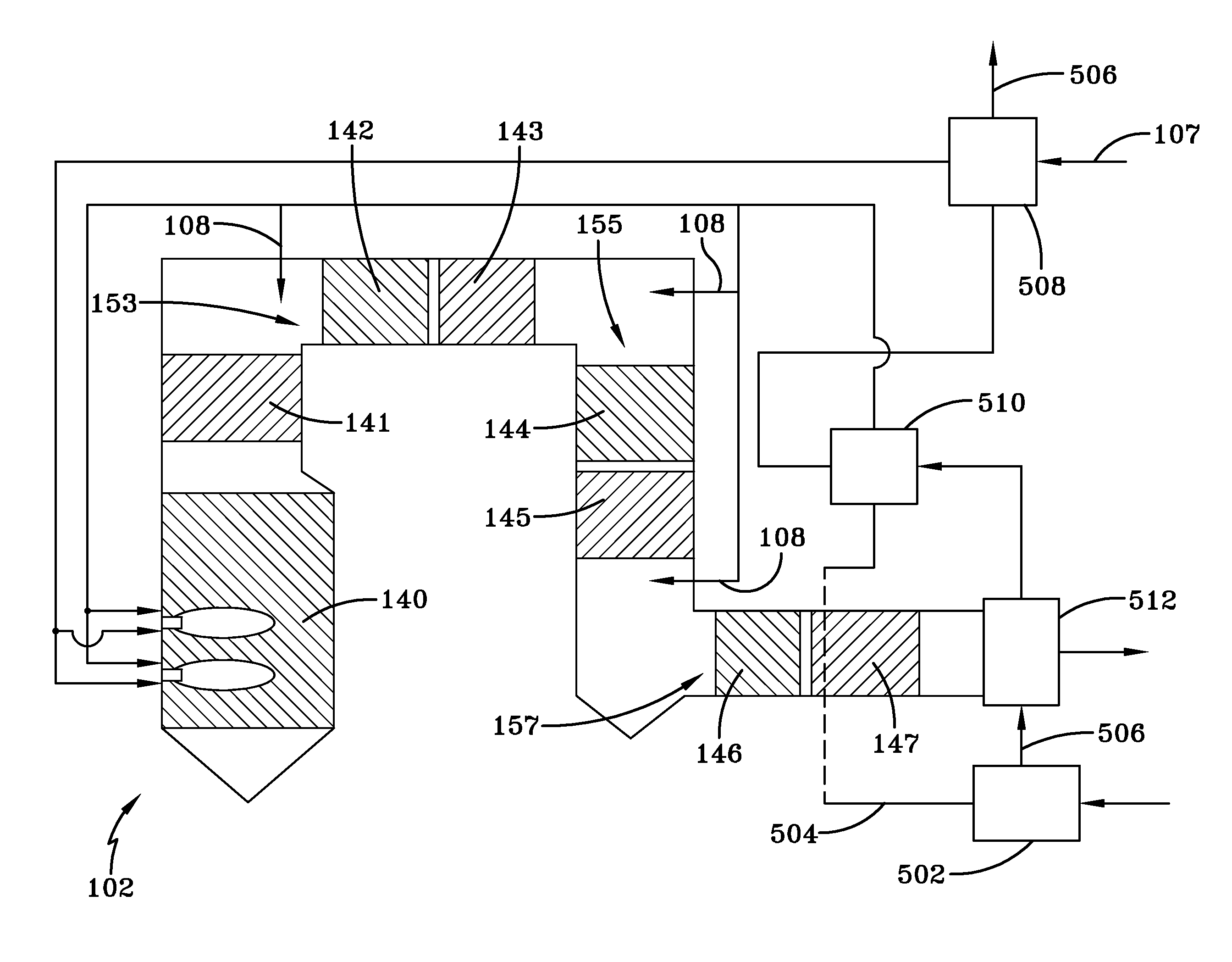
[0053]Desirable furnace exit gas temperatures are typically in the range of about 2200 to 2550° F. (1200 to 1400° C.), primarily based on tube fouling considerations. Hence, somewhat higher gas temperatures may be acceptable in gas-to-steam heat exchangers, in particular by those using state-of-the-art boiler tube materials, depending upon local heat transfer coefficients. For the purpose of illustration in this example, gas temperatures up to about 2700° F. (1482° C.) entering a gas-to-steam heat exchanger are analyzed.

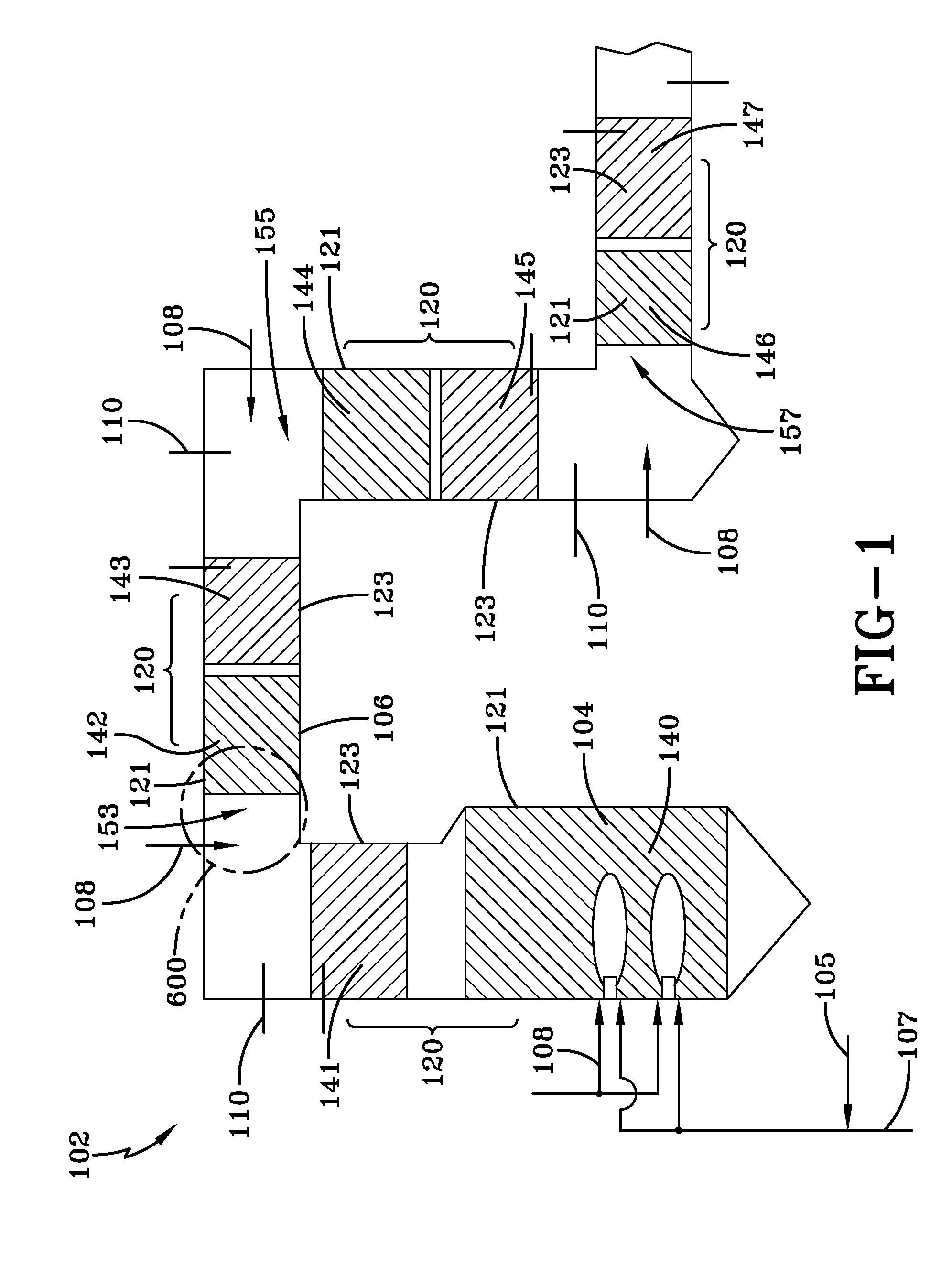
[0054]Possible operating parameters for the above embodiments of this disclosure are expressed through the following example. A high volatile Bituminous coal with properties listed in Table 1 burned with 100% pure oxygen in a system according to the embodiment illustrated by FIG. 1 of the disclosure burns to produce steam to a single reheat turbine-generator generating 600 MW (net) of electrical power. The total heat exchange rate between gas and water / steam is 4700 ...


PUM


Abstract

This disclosure includes a system and method of controlling fuel combustion including providing a system, measuring a property, and providing oxygen and fuel in response to the property. The system includes a furnace arranged and disposed to receive fuel and oxygen and combust the fuel and the oxygen to form a combustion fluid, a plurality of heat exchanger sections arranged and disposed to receive heat from the combustion fluid, and a plurality of oxygen injectors arranged and disposed to controllably provide oxygen to the combustion fluid to adjust composition of the combustion fluid and temperature of the combustion fluid. The property measured is selected from the group consisting of temperature of the combustion fluid, composition of the combustion fluid, temperature of the heat exchanger sections, and combinations thereof and is performed in close proximity to the oxygen injectors.

Description

CROSS-REFERENCE TO RELATED APPLICATIONS[0001]This Application is related to application Ser. No. 12 / 238,612, entitled “OXY / FUEL COMBUSTION SYSTEM WITH LITTLE OR NO EXCESS OXYGEN”, filed contemporaneously with this Application on Sep. 26, 2008, assigned to the assignee of the present disclosure and which is herein incorporated by reference in its entirety, application Ser. No. 12 / 238,632, entitled “COMBUSTION SYSTEM WITH STEAM OR WATER INJECTION”, filed contemporaneously with this Application on Sep. 26, 2008, assigned to the assignee of the present disclosure and which is herein incorporated by reference in its entirety, application Ser. No. 12 / 238,644, entitled “COMBUSTION SYSTEM WITH PRECOMBUSTOR”, filed contemporaneously with this Application on Sep. 26, 2008, assigned to the assignee of the present disclosure and which is herein incorporated by reference in its entirety, application Ser. No. 12 / 238,671, entitled “CONVECTIVE SECTION COMBUSTION”, filed contemporaneously with this ...

Claims


Application Information

Patent Timeline
Patent Type & Authority Patents(United States)
IPC IPC(8): F23L15/00F23N5/02
CPCF23C9/003F23N5/003F23L7/007F23C2202/20Y02E20/344F23N2037/28F23N2237/28Y02E20/34
Inventor D'AGOSTINI, MARK DANIEL
Owner AIR PROD & CHEM INC
Why Eureka
Try Eureka