Arrangement for cooling of oil in a gearbox for a vehicle

a technology for gearboxes and oil, which is applied in the direction of gearing details, machines/engines, mechanical apparatuses, etc., can solve the problems of affecting the service life of the cooling system, the inability to provide a relatively long oil line in the vehicle, and the inability to provide coolant at a low temperature. , to achieve the effect of optimal service li

Active Publication Date: 2012-11-27
SCANIA CV AB
View PDF5 Cites 6 Cited by
  • Summary
  • Abstract
  • Description
  • Claims
  • Application Information

AI Technical Summary

Benefits of technology

[0006]The object of the present invention is to provide an arrangement which makes it possible for the oil in a gearbox in a vehicle to be cooled to a temperature such that the components of the gearbox will achieve a substantially optimum service life.
[0007]This object is achieved with an arrangement for cooling oil in the gearbox of a vehicle via a cooling circuit arrangement that brings a coolant to the oil used in the gearbox for cooling the oil, according to the invention. The oil and the components in a gearbox usually have optimum characteristics when they are at a relatively low temperature. Keeping the oil and the components in a gearbox substantially continuously at such a temperature during operation of a vehicle involves the oil having to be cooled by coolant which is at a lower temperature than the desired temperature of the oil and of the components. The coolant in the combustion engine's cooling system is normally at too high a temperature to be able to cool the oil in the gearbox to the desired temperature. According to the invention, a coolant circuit with a circulating coolant which is cooled in a radiator element which has a cooling air flow passing through it is therefore used. The more slowly the coolant is led through the radiator element, the longer the time during which it is cooled by the air flowing through the radiator element. Regulating the coolant flow through the radiator element in a suitable manner makes it possible for the coolant to be substantially always at a low enough temperature when it leaves the radiator element for it to be able to cool the oil in the oil cooler in a desired manner. With such cooling of the oil, the components of the gearbox can substantially always be provided with good lubrication and cooling. The components may thus achieve an optimum service life.
[0009]According to another embodiment, the oil cooler is a counterflow heat exchanger. The coolant and the oil are led in opposite directions through the oil cooler which takes the form of a counterflow heat exchanger. The oil is thus led out from the oil cooler where the cold coolant is led into the oil cooler. This makes it possible to cool the oil to a temperature close to the temperature of the cold coolant.

Problems solved by technology

A disadvantage of such positioning of the oil cooler is that the oil has to be conveyed forward from the gearbox to the front portion of the vehicle.
This entails having to provide relatively long oil lines in the vehicle.
The coolant can therefore not usually have a low enough temperature imparted to it for it to be able to cool the oil in the gearbox in an optimum manner.

Method used


Image

  • Arrangement for cooling of oil in a gearbox for a vehicle
  • Arrangement for cooling of oil in a gearbox for a vehicle
  • Arrangement for cooling of oil in a gearbox for a vehicle

Examples


Embodiment Construction

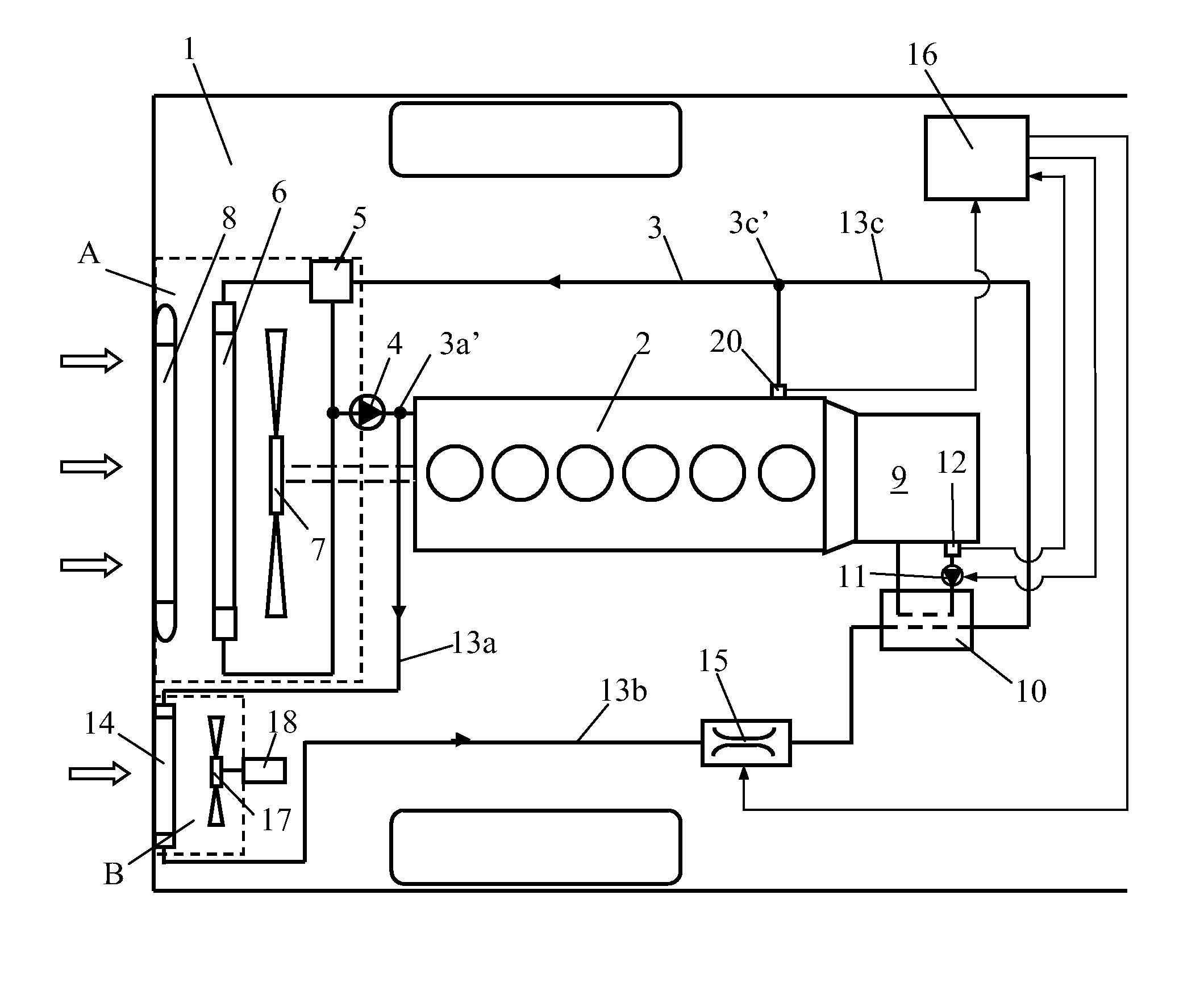
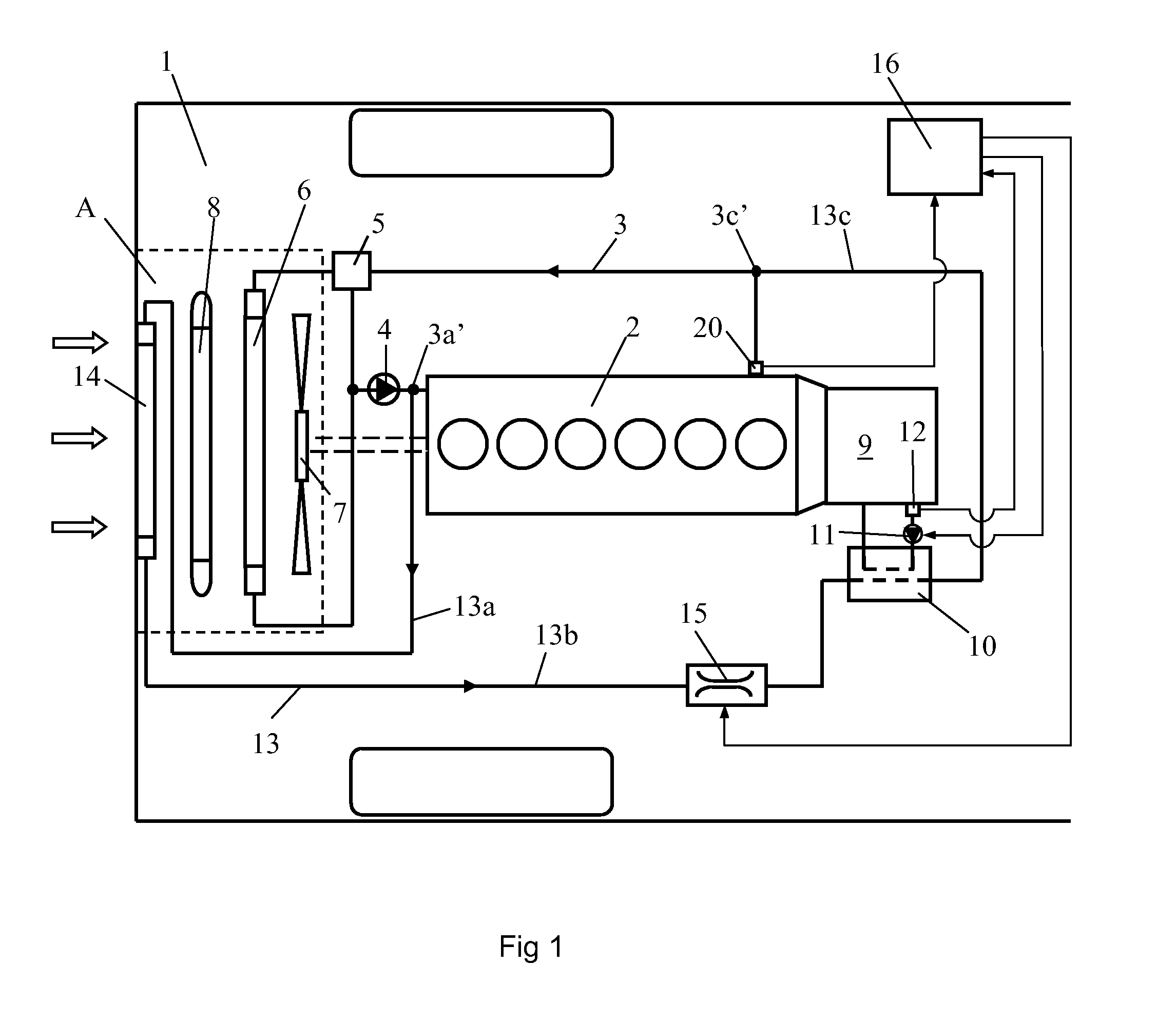
[0017]FIG. 1 depicts schematically a vehicle 1 powered by a supercharged combustion engine 2. The vehicle 1 may be a heavy vehicle powered by a supercharged diesel engine. The combustion engine 2 is cooled in a conventional manner by a cooling system 3 which contains a circulating coolant. The coolant is circulated in the cooling system 3 by a coolant pump 4. The cooling system 3 comprises a thermostat 5 adapted to directing the coolant to a radiator 6 or alternatively back to the combustion engine 2 when the temperature of the coolant is below a specific value. The radiator 6 is arranged in an air passage A at a front portion of the vehicle 1. The coolant is cooled in the radiator 6 by the air which flows through the air passage A. A radiator fan 7 is adapted to providing a forced air flow in a specific direction through the air passage A. The radiator fan 7 is driven by the combustion engine 2 via a suitable connection. A charge air cooler 8 is arranged in the air passage A upstre...


PUM


Abstract

An arrangement for cooling oil in a gearbox in a vehicle which is powered by a combustion engine, the arrangement including an oil cooler, an oil system configured to circulate oil between the gearbox and the oil cooler, and a coolant circuit configured and operable to lead coolant to the oil cooler. The coolant circuit includes a radiator element for cooling the coolant and a line to lead the cooled coolant from the radiator element to the oil cooler. The coolant circuit has a flow-regulator to regulate the coolant flow through the radiator element for imparting to the coolant a temperature which makes possible a desired cooling of the oil in the oil cooler.

Description

CROSS REFERENCE TO RELATED APPLICATION[0001]The present application is a 35 U.S.C. §§371 national phase conversion of PCT / SE2008 / 051095, filed Sep. 29, 2008, which claims priority of Swedish Application No. 0702241-1, filed Oct. 5, 2007, the disclosure of which is incorporated by reference herein. The PCT International Application was published in the English language.BACKGROUND TO THE INVENTION, AND STATE OF THE ART[0002]The present invention relates to an arrangement for cooling of oil in a gearbox in a vehicle via a separate cooling circuit.[0003]The oil in a vehicle's gearbox has to be at a relatively low temperature if the components intended to be lubricated and cooled by the oil are to achieve a long service life. A known way of ensuring that the oil in the gearbox will substantially continuously be at a low enough temperature during operation of the vehicle is to use an air-cooled oil cooler for cooling the oil. However, for it to be able to provide effective cooling of the ...

Claims


Application Information

Patent Timeline
Patent Type & Authority Patents(United States)
IPC IPC(8): F01P11/08F16H57/04
CPCF01P7/165F16H57/0413F01P2003/182F01P2007/143F01P2060/045F01P2003/187F01P3/20
Inventor SODERBERG, ERIKKARDOS, ZOLTAN
Owner SCANIA CV AB
Why Eureka
Try Eureka