Multistage jounce bumper

a bumper and multi-stage technology, applied in the field of multi-stage jounce bumpers, can solve the problems of load management problems, wear and tear of the conventional jounce bumper cushion and its related dampers, and achieve the effect of improving the feel and control of the ride, and absorbing additional jounce force and energy

a bumper and multi-stage technology, applied in the field of multi-stage jounce bumpers, can solve the problems of load management problems, wear and tear of the conventional jounce bumper cushion and its related dampers, and achieve the effect of improving the feel and control of the ride, and absorbing additional jounce force and energy

US8317172B2Active Publication Date: 2012-11-27GM GLOBAL TECH OPERATIONS LLC

Image

  • Multistage jounce bumper
  • Multistage jounce bumper
  • Multistage jounce bumper

Examples


Embodiment Construction

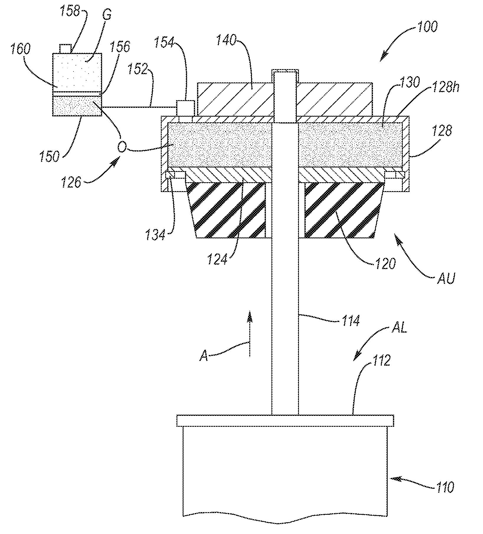
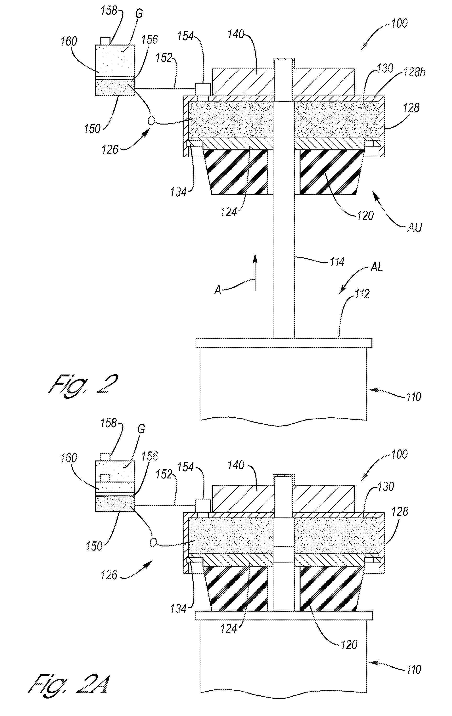
[0024]Referring now to the Drawing, FIG. 2 through FIG. 6 depict various aspects of structure and function of a multistage jounce bumper according to the present invention. The multistage jounce bumper is a novel synthesis of a jounce bumper cushion, a tunable hydraulic jounce bumper, and related damper components. The resulting expanded jounce management provides improved feel of the ride and enhances the capacity for load control in high-energy, uneven terrain inputs. While any type of damper may be used with the present invention (see discussion of dampers hereinabove), the most preferred form of damper is a strut.

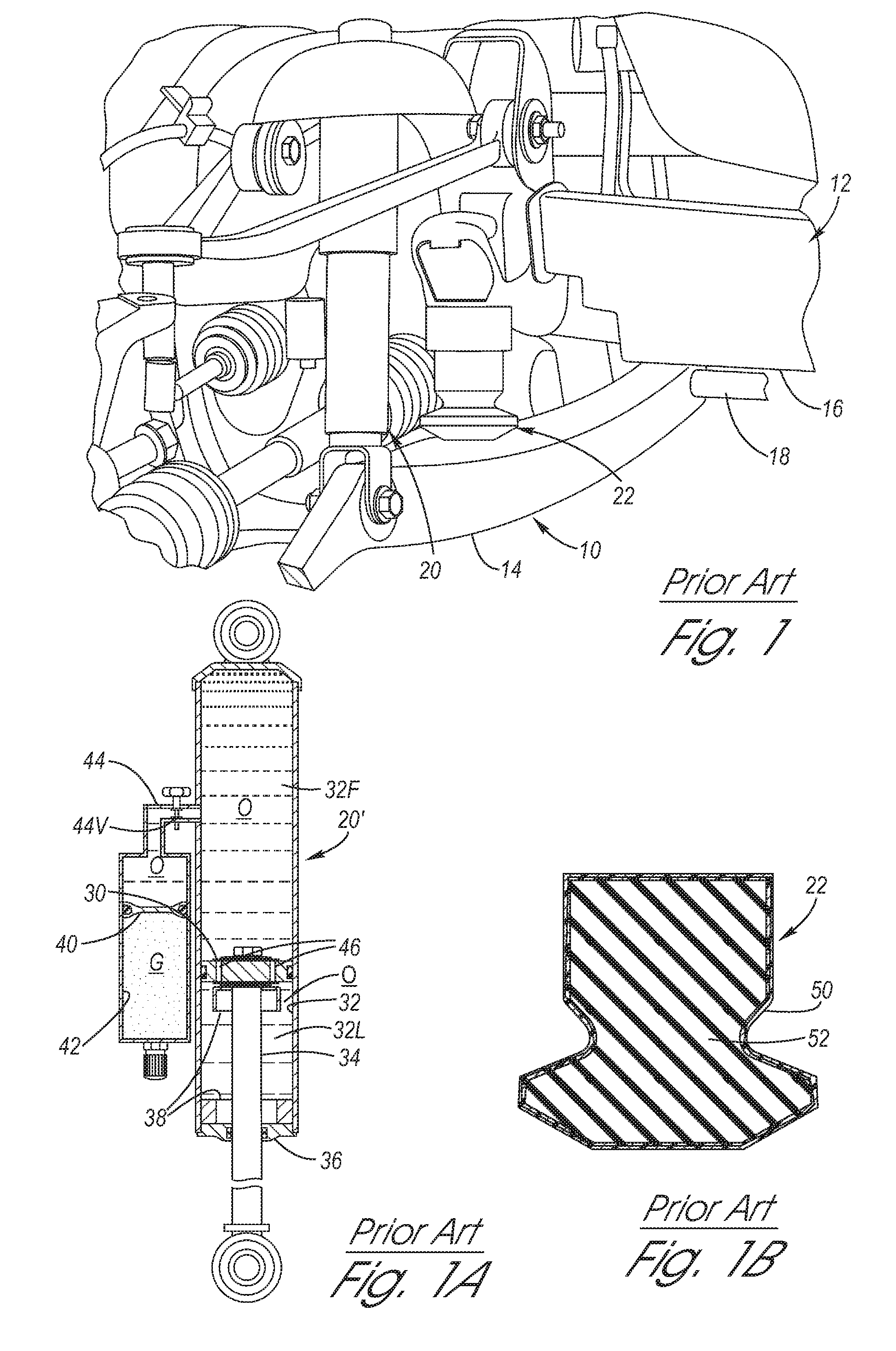
[0025]Referring firstly to FIG. 2, the multistage jounce bumper 100 according to the present invention is depicted. A lower aspect AL of the multistage jounce bumper 100 consists of a damper 110 (i.e., a strut or shock absorber) which is connected to a knuckle or control arm of the suspension system as generally depicted with respect to the shock absorber 20 of FIG. 1, ...


PUM


Abstract

A multistage jounce bumper, including a jounce bumper cushion integrated with a hydraulic jounce bumper, wherein provided are the damping characteristic of the hydraulic jounce bumper and the damping / spring characteristics of a jounce bumper cushion. The hydraulic jounce bumper hydraulic response is tunable via adjustment of hydraulic flow with respect to a communicating hydraulic fluid reservoir. When maximum jounce is approached, jounce force and energy are exchanged, at a first stage, with the jounce bumper cushion, then at a predetermined compression, jounce force and energy are exchanged, at a second stage, with the hydraulic jounce bumper. Thereafter, a mechanical abutment is provided as a third stage of jounce management.

Description

TECHNICAL FIELD[0001]The present invention relates to automotive suspension systems, particularly the bumper mount, the jounce bumper, and conventional dampers. More particularly, the present invention relates to a multistage jounce bumper which is a synthesis of a jounce bumper cushion and a hydraulic jounce bumper, the combination providing enhanced suspension system energy absorption and improved ride characteristics.BACKGROUND OF THE INVENTION[0002]Motor vehicle suspension systems are configured so that the wheels are able to follow elevational changes in the road surface as the vehicle travels therealong. When a rise in the road surface is encountered, the suspension responds in “jounce” in which the wheel is able to move upwardly relative to the frame of the vehicle. On the other hand, when a dip in the road surface is encountered, the suspension responds in “rebound” in which the wheel is able to move downwardly relative to the frame of the vehicle. In either jounce or reboun...

Claims


Application Information

Patent Timeline
27 Nov 2012
Publication
US8317172B2
IPC
F16F9/00
CPC
B60G17/06; B60G17/08; F16F9/58; F16F13/06; B60G2202/24; B60G2204/129
Inventors
QUINN, SHAWN G.; FADLER, GREGORY J.