Vibration damping system

a technology of vibration damping and damping body, which is applied in the direction of shock absorbers, machine supports, other domestic objects, etc., can solve the problems of weak tensile force in the laminating direction and vibration damping system of the type, so as to prolong the service life and improve the fatigue strength of the laminated body

Inactive Publication Date: 2012-11-27
BRIDGESTONE CORP
View PDF20 Cites 11 Cited by
  • Summary
  • Abstract
  • Description
  • Claims
  • Application Information

AI Technical Summary

Benefits of technology

[0006]It is an object of the present invention to further improve the vibration damping system according to the applicant's earlier proposal, in such a manner that, even if partial tensile force is generated upon occurrence of the prying deformation, or the pre-compression function deteriorates due to the wear of the displacement restriction member, the vibration damping system as being applied with the tensile force is still capable of preventing damages to the laminated rubber body comprised of hard members and soft members, and suppressing dislocation in the shearing direction.

Problems solved by technology

However, while exhibiting high durability against compression force in the laminating direction, the vibration damping system of the type wherein hard plates and soft members are alternately laminated with each other is very weak to tensile force in the laminating direction.

Method used


Image

  • Vibration damping system
  • Vibration damping system
  • Vibration damping system

Examples


first embodiment

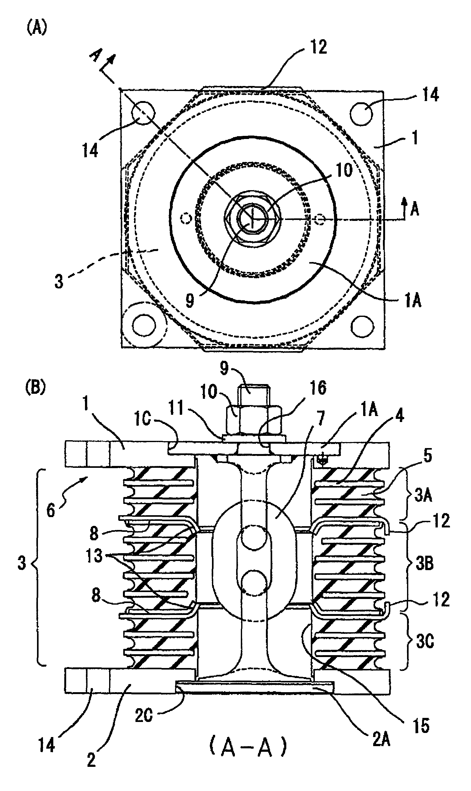
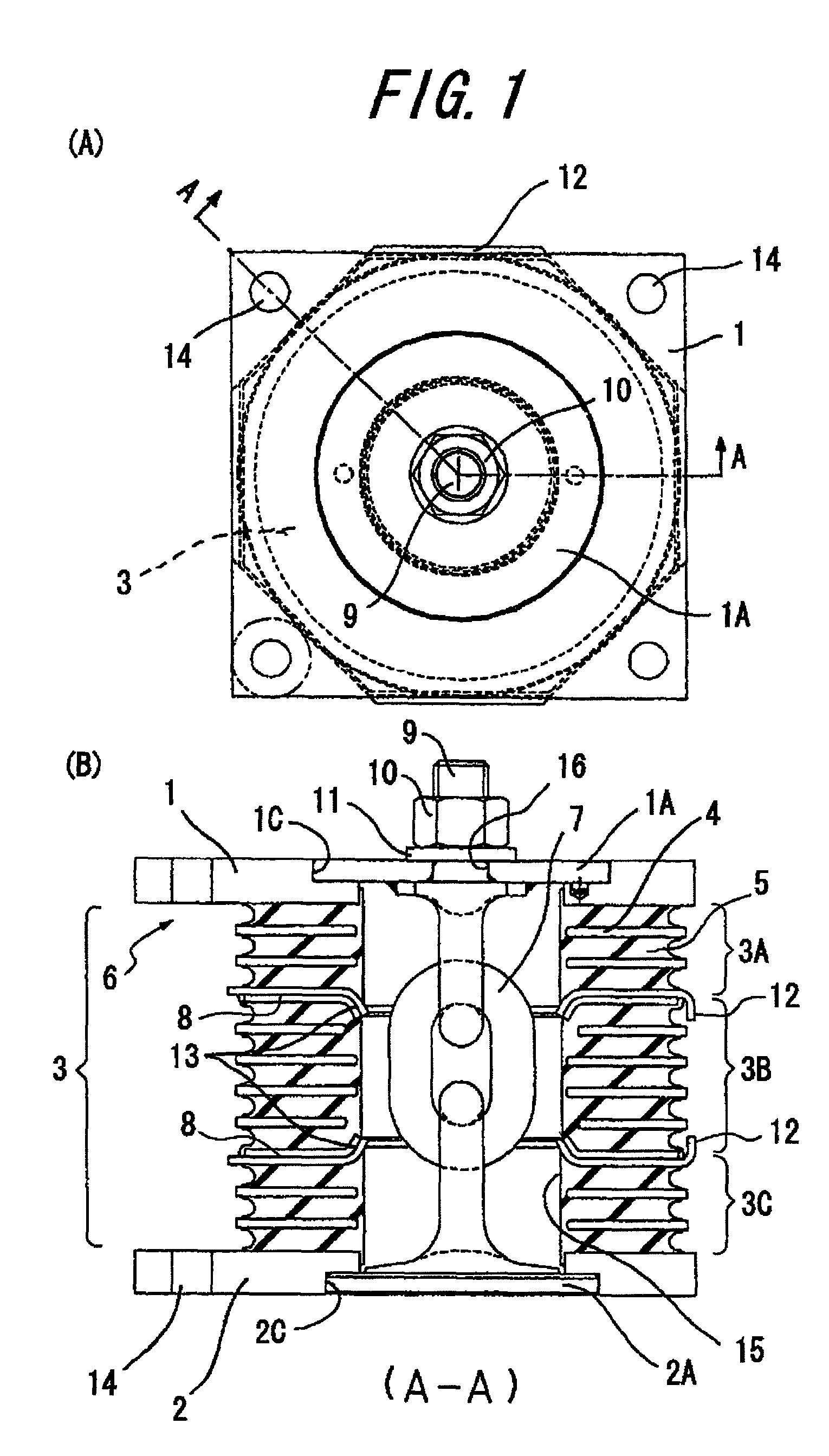
[0049]As shown in FIG. 1(B), hard plates 4 having rigidity and soft members 4 having viscoelasticity are alternately laminated to form a laminated body 3, and upper and lower shoe members 1, 2 are arranged on both end portions of the laminated body 3 to form the vibration damping body 6. The hard plates 4 may be comprised of a suitable metal material, such as iron, aluminum or the like. Besides a metal material, the hard plates 4 may be comprised of a resin material, such as nylon, and adhered to the soft members is the case with the metal material.

[0050]The soft members 5 having viscoelasticity are generally formed by molding various types of vulcanized rubber as the raw material. Such rubber material may include, for example, ethylene-propylene rubber (EPR, EPDM), nitrile rubber (NBR), butyl rubber, halogenated butyl rubber, chloroprene rubber (CR), natural rubber (NR), isoprene rubber (IR), styrene-butadiene rubber (SBR), butadiene rubber (BR), and a blend thereof. Alternatively,...

second embodiment

[0081]FIGS. 4(A) and 4(B) are a plan view and a longitudinal sectional view of the vibration damping system according to a modification of the above-described embodiment of the present invention, respectively. In this modified embodiment, each dividing location of the vibration damping body 6, i.e., each parting face 8 in the laminated body 3, is covered over the entire periphery and sealed from outside, by a cover member 21 that is made of a suitable material, such as rubber film body. The cover member 21 functions as a dust cover for preventing entry of foreign matters into a space surrounding the parting face 8. The cover member 21 may be comprised of a toroidal rubber film having a bellow shape with a single protrusion. It is further preferred that the cover member is brought into contact with the outer periphery of the vibration damping body 6, bridging across the parting faces 8, under its own resilient shrinkage force, from the viewpoint of achieving a sufficiently tight cont...


PUM


Abstract

A vibration damping system includes a laminated body (3) formed by alternately laminating rigid hard plates (4) and viscoelastic soft plates (5), and pair of shoe plates (1, 2) at both ends in the laminating direction of the laminated body (3), to form a vibration damping body (6). The show plates (1, 2) are connected to each other by a displacement restriction member (7), so as to applying a pre-compression to the laminated body. The vibration damping body (6) is divided into a plurality of segments (3A, 3B, 3C) in the laminating direction, for allowing the vibration-proof main body (6) to be separated and displaced at the parting faces (8), without causing an excessive tensile force in the vibration damping system, even if the displacement restriction member (7) has worn to degrade the pre-compression function and a tensile force is applied due to a prying deformation. Thus, the soft members (5) of the laminated body (3) are effectively protected from isostatic fracture, to provide a significantly improved durability of the vibration damping system.

Description

CROSS REFERENCE TO RELATED APPLICATIONS[0001]This application is a National Stage of International Application No. PCT / JP2007 / 068416 filed Sep. 21, 2007, claiming priority based on Japanese Patent Application Nos. 2006-256573 and 2007-220331, filed Sep. 22, 2006 and Aug. 27, 2007, respectively, the contents of all of which are incorporated herein by reference in their entirety.TECHNICAL FIELD[0002]The present invention relates to a vibration damping system comprising a vibration damping body including a laminated body wherein a plurality of hard plates having rigidity and a plurality of soft members having viscoelasticity are alternately laminated with each other, and a pair of shoe plates on both end portions of the laminated body in the laminating direction, and further comprising a displacement restriction member for connecting the shoe plates with each other for providing a pre-compression to the laminated body.BACKGROUND ART[0003]There have been proposed various types of vibrat...

Claims


Application Information

Patent Timeline
Patent Type & Authority Patents(United States)
IPC IPC(8): F16F1/40F16F7/00
CPCF16F1/40F16F2230/007
Inventor KAWADA, MASAYOSHI
Owner BRIDGESTONE CORP
Why Eureka
Try Eureka