Turbine airfoil with micro cooling channels

a technology of airfoils and turbines, which is applied in the direction of blade accessories, machines/engines, mechanical equipment, etc., can solve the problems of high defect rate of airfoils, limited power and performance of gas turbine engines, and high brittle ceramic materials

Active Publication Date: 2012-11-27
SIEMENS ENERGY INC +1
View PDF10 Cites 53 Cited by
  • Summary
  • Abstract
  • Description
  • Claims
  • Application Information

AI Technical Summary

Benefits of technology

[0013]Film cooling holes that open onto the airfoil surface can be formed while the airfoil is being produced using the TLM process so that drilling is not required after the airfoil has been formed. Complex film cooling hole openings can also be formed since the drilling by a laser or the formation by EDM process is not required. Film cooling holes with rounded sides and varying expansions can be produced using the TLM process while the airfoil is being produced without additional processing steps.

Problems solved by technology

In early engines, the power and performance of the gas turbine engines were limited by the material characteristics on operating temperature.
One major problem with the investment casting process used to produce a modern air cooled turbine airfoil is that the defect rate of airfoils is very high due to the ceramic cores being broken during or after the casting process to create the core, or during the casting process when the molten metallic material flows around the core details.
The cores are made from a ceramic material which is very brittle.
Ceramic cores are limited in size due to the granular structure of the material.
Smaller sizes are not capable of being produced that can create the smaller cooling features under the 0.010 inches.
However, air cooled turbine airfoils using these CFD optimized designs cannot be produced using the current investment casting process because of the minimum core size.

Method used


Image

  • Turbine airfoil with micro cooling channels
  • Turbine airfoil with micro cooling channels
  • Turbine airfoil with micro cooling channels

Examples


Embodiment Construction

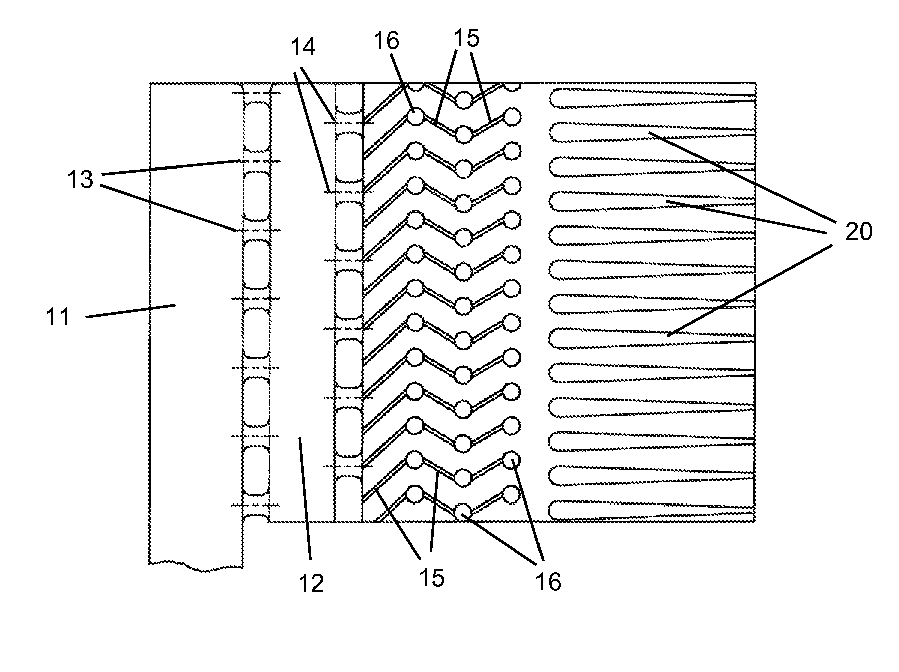
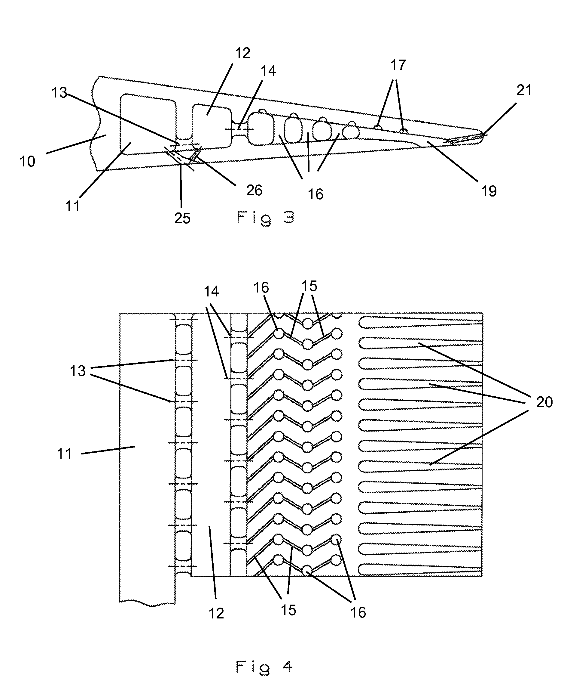
[0018]The present invention is a turbine airfoil used in a gas turbine engine, where the turbine airfoil includes an internal cooling air circuit and film and exit cooling holes that are produced using the Tomo Lithographic Molding (TLM) process developed by Mikro Systems, Inc. of Charlotte, N.C. that can produce details much smaller than can be produced using the prior art investment casting process. The TLM process builds up the airfoil in layers without using casting or cores to produce molds that include casting. The airfoil is created with the internal passages and other features during the process that creates the entire airfoil.

[0019]FIG. 3 shows a cross section of the trailing edge cooling circuit from a top view that is formed using the TLM process of the present invention. The airfoil 10 includes a first radial channel 11 and a second radial channel 12 located aft and separated by a first row of metering holes 13, where the metering holes are offset from the normal central...


PUM


Abstract

An air cooled turbine airfoil having micro cooling air passages formed within the airfoil that is of such size that the present day investment coating process cannot be used. The internal cooling air features of the airfoil are formed using the Tomo Lithographic Molding (TLM) process. The TLM process is a low pressure casting process that can produce precise micro-features integral to macro-scale structures using any of the exotic alloys or other metallic materials currently being used in airfoil production. The normal internal cooling air passages as well as very small features such as trip strips, pin fins, dimples, pedestals and enclosed passages such as film holes can be produced using the TLM process.

Description

FEDERAL RESEARCH STATEMENT[0001]None.CROSS-REFERENCE TO RELATED APPLICATIONS[0002]None.BACKGROUND OF THE INVENTION[0003]1. Field of the Invention[0004]The present invention relates generally to air cooled turbine airfoils, and more specifically to turbine airfoils with micro cooling channels.[0005]2. Description of the Related Art including information disclosed under 37 CFR 1.97 and 1.98[0006]In early engines, the power and performance of the gas turbine engines were limited by the material characteristics on operating temperature. To allow for higher turbine inlet temperatures, cooling were used in the early stage airfoils to allow for gas flow temperatures to actually exceed the material thermal limits. The first generation of air cooled turbine airfoils included radial passages extending from a supply channel formed within the blade root and through the airfoil portion to eventually discharge out the blade tip. These passages were straight and produced convection cooling only.[0...

Claims


Application Information

Patent Timeline
Patent Type & Authority Patents(United States)
IPC IPC(8): F01D5/18
CPCF01D5/186F05D2230/14F05D2230/211F05D2240/122F05D2240/304
Inventor DOWNS, JAMES P
Owner SIEMENS ENERGY INC
Why Eureka
Try Eureka