
Automatic collimation surveying apparatus having image pick-up device

a surveying apparatus and collimation technology, applied in the field of surveying equipment, can solve the problems of inability to carry out efficient measurement, heavy work load on the operator, and insatiable work efficiency

Inactive Publication Date: 2006-07-25
SOKKOIA COMPANY LIMITED
View PDF16 Cites 29 Cited by
  • Summary
  • Abstract
  • Description
  • Claims
  • Application Information

AI Technical Summary

Benefits of technology

[0009]In order to solve the above-described problems, it is therefore an object of the present invention to provide an automatic collimation surveying apparatus that can lighten a work load for an operator to collimate points of measurement, and at the same time is able to efficiently measure a number of points of measurement, without any heavy load with respect to an object to be measured, of a large-scaled structure, with only a single surveying apparatus and by a single operator.

Problems solved by technology

Consequently, there is a problem in that work efficiency is not satisfactory since, after images and surveying data are obtained at all of the plurality of points, positions of the respective points of measurement of a large-scaled structure are obtained, by using a personal computer, on the basis of the image and surveying data that are stored in a memory medium.
Furthermore, since it is necessary for an operator to manually carry out collimation with respect to the points of measurement, there is another problem in that the work load applied on the operator is heavy and efficient measurement can not be carried out.
Therefore, the work load applied to the operator is heavy, and no efficient measurement can be carried out.
However, since such an automatic collimation unit only functions after its sensor catches reflection light from the target, it is necessary for the operator at least to catch a target in the vicinity of the center of a rectile line (cross-shaped lines) in the field of view of a telescope, and a work load which is almost similar to that of manual collimation is required.

Method used


Image

  • Automatic collimation surveying apparatus having image pick-up device
  • Automatic collimation surveying apparatus having image pick-up device
  • Automatic collimation surveying apparatus having image pick-up device

Examples


Embodiment Construction

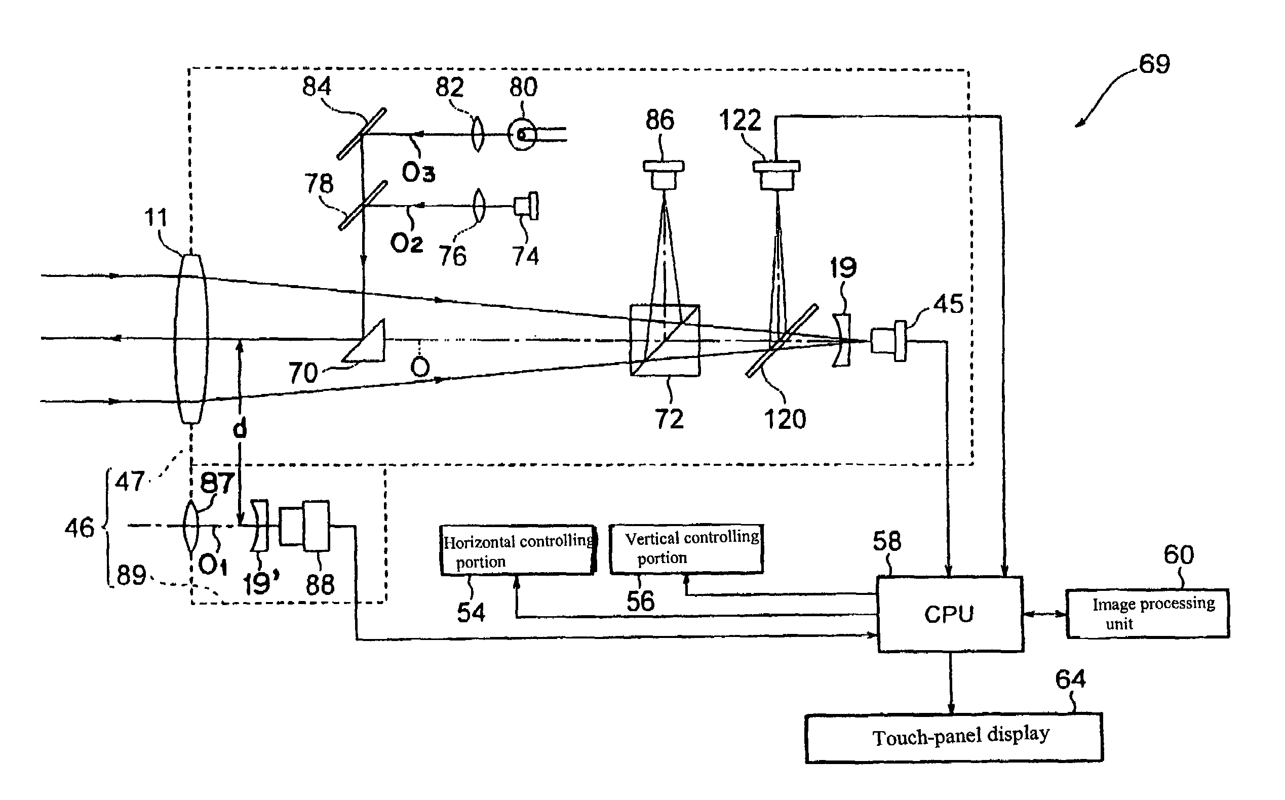
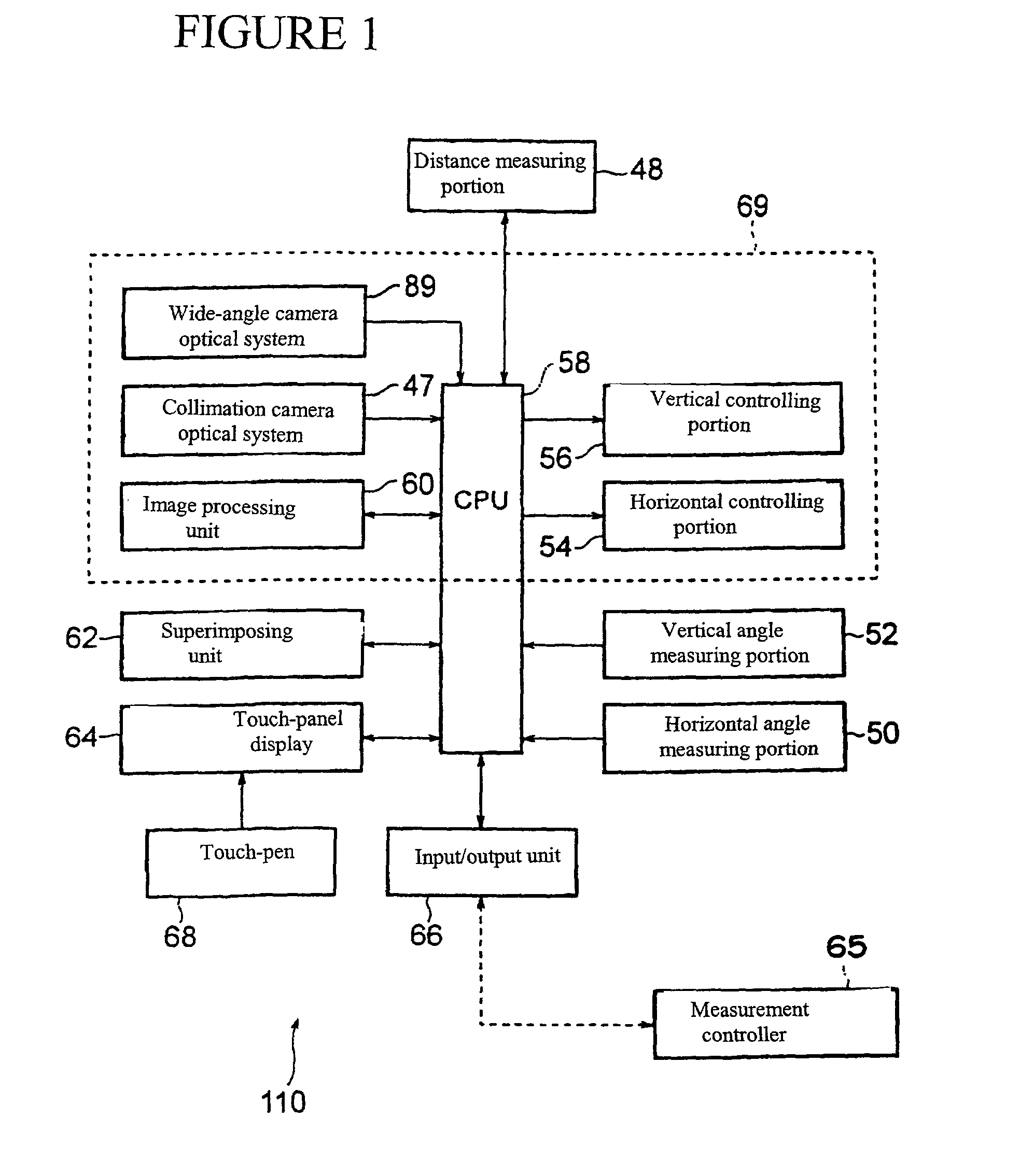
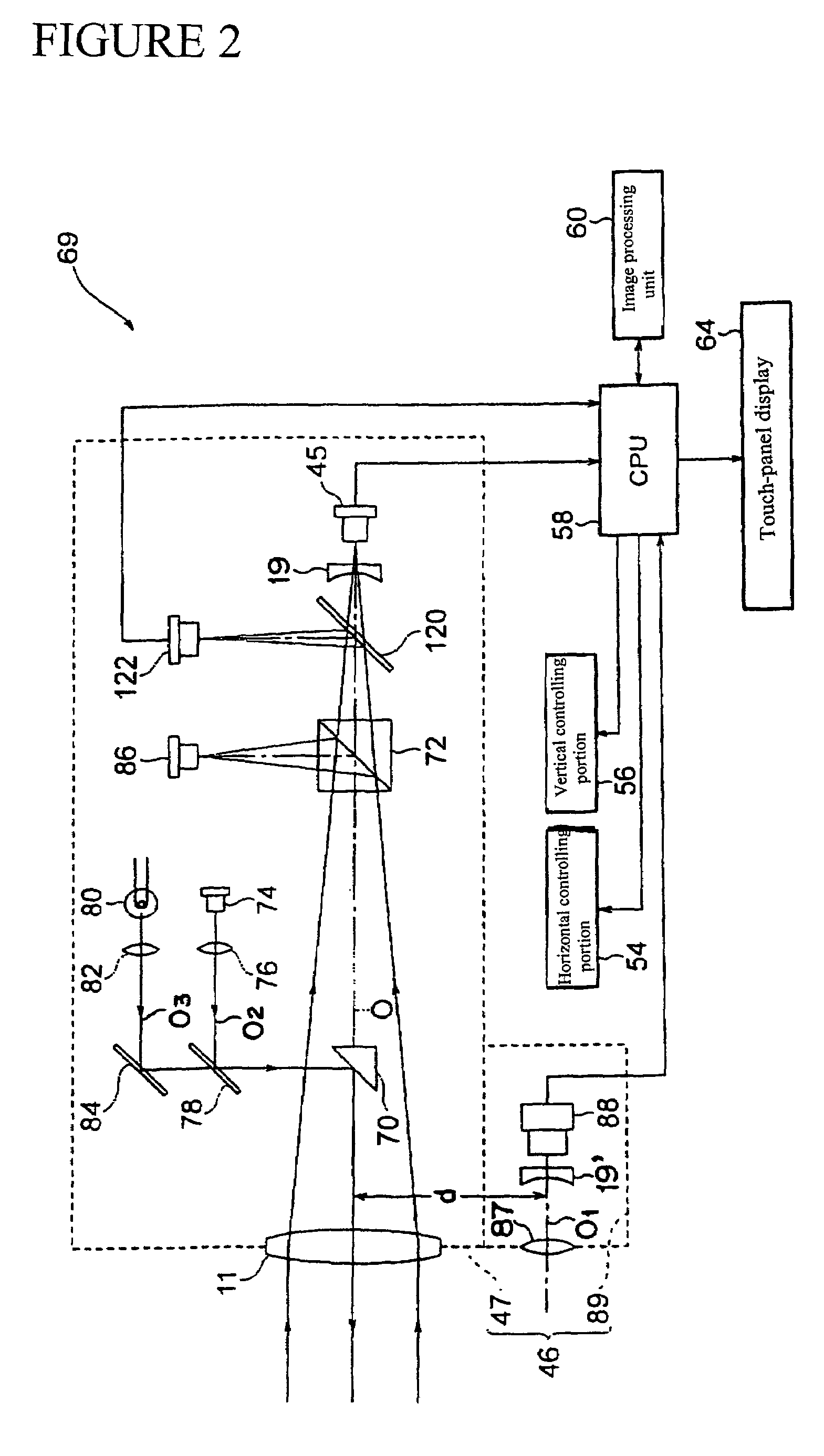
[0040]As shown in FIG. 1, FIG. 2 and FIG. 3, a telescope 46 of a surveying apparatus 110 according to the present embodiment is provided with, as shown in FIG. 1, FIG. 2 and FIG. 3, a wide-angle camera optical system 89 which functions as a pick-up device for picking up an object to be measured, at a wide-angle range of a low magnification ratio, in addition to a collimation camera optical system 47 which functions as a pick-up device for picking up an object to be measured at a high magnification ratio. And, in the surveying apparatus 110, as shown in FIG. 3, a horizontal rotation axis 43 is horizontally rotatably attached on a leveling-up base 40, and a telescope 46 is vertically rotatably attached between erected portions 44 erected on the horizontal rotation axis 43.

[0041]Also, as shown in FIG. 1, the surveying apparatus 110 according to the embodiment includes, as in the total station, a distance measuring portion (optical wave range finder) 48 for measuring a distance to a poi...


PUM


Abstract

An automatic collimation surveying apparatus is provided with a collimation camera optical system (47) of a high magnification ratio; a wide-angle CCD camera optical system (89) having a wide field of view; a touch-panel display (64) for displaying an image picked up by both CCD camera optical systems; an image processing unit (60) for discriminating points of measurement from the above-described image; a touch-pen for pointing out points of measurement on the above-described image; and an automatic collimation unit (69) for automatically collimating the pointed-out points of measurement. In addition, illumination light from light source (80) is concurrently used as collimation light and is aligned so as to be emitted along the collimation axis (O) of a collimation camera optical system. The surveying apparatus can be remotely controlled from a measurement controller such as a peripheral personal computer. The surveying apparatus allows a number of point-of-measurement positions to be efficiently measured on a large-scaled structure by a single operator.

Description

FIELD OF THE INVENTION[0001]The present invention relates to a surveying apparatus provided with a pick-up device such as a CCD camera, and an image processing unit, and in particular to a surveying apparatus suited to measurement of respective positions of a large-scaled structure such as a bridge, a ship, or a tunnel.BACKGROUND OF THE INVENTION[0002]Japanese Unexamined Patent Publication No. Hei-11-325883 discloses a total surveying station provided with an image pick-up device has existed. The telescope of the total station disclosed by the Publication is provided, as shown in FIG. 18, with an object lens 11, a focusing lens 12, a holoprism 13 to make an image erect, a beam splitter 16, a reticle 14, and eyepiece lens 15 on the optical axis, and is further provided with a CCD camera 17 for receiving light reflected by the beam splitter 16 in an orthogonal direction, and an optical system 18 for a range finder, which is disposed rearward of the object lens 1. An image picked up by...

Claims


Application Information

Patent Timeline
IPC IPC(8): H04N7/18H04N9/47G01C15/00
CPCG01C15/00
Inventor SHIMOYAMA, YUUJIOGAWA, KUNITOSHIKURIYAMA, GEN
Owner SOKKOIA COMPANY LIMITED
Learn More