Self-assembled electrical contacts

a technology of electrical contacts and self-assembling, which is applied in the direction of sustainable manufacturing/processing, final product manufacturing, printed circuit manufacturing, etc., can solve the problems of individual devices, inability to handle and deterministically place components with reasonable efficiency and cost, and inability to meet the needs of small components

Inactive Publication Date: 2012-11-27
UNITED STATES OF AMERICA THE AS REPRESENTED BY THE SEC OF THE ARMY
View PDF1 Cites 16 Cited by
  • Summary
  • Abstract
  • Description
  • Claims
  • Application Information

AI Technical Summary

Problems solved by technology

However, below a certain component size scale, these techniques typically cannot handle and deterministically place components with reasonable efficiency and cost.
Modern IC and MEMS manufacturing processes produce devices much smaller than 300 μm, but current assembly methods typically cannot handle such small, individual devices.
However, a limitation with such methods is that other forces can overcome the inertial or gravitational forces required to release parts at the desired stage in a pick and place process.
A further limitation is that the deterministic handling of parts becomes infeasible as the number of parts increases, because of the serial nature of such methods.
However, a limitation exists with the use of a laminated structure, in that the application of this method to large numbers of assembly sites would be infeasible.
Another limitation is that strong magnetic fields remain permanently in the vicinity of each part following assembly, which would affect the electromagnetic characteristics of any device and may be incompatible with many device technologies.
A further limitation is that additional process steps are required to form permanent mechanical and electrical connections, which increase cost.
However, the limitation remains of requiring additional process steps to form permanent mechanical and electrical connections, which increases cost.
A limitation with these methods is only gravity will keep the parts in desired wells following assembly, and therefore the parts may disengage from the wells upon further handling.
The same limitation also exists in that post processes are required to form permanent mechanical and electrical connections, which is an example of further handling.
Limitations with these approaches include high costs associated with the difficulty of providing temporary electrical connections to addressable electrode structures on the template, where the template is typically submerged in a fluid containing the parts to be assembled.
The same limitation also exists in that post processes are required to form permanent mechanical and electrical connections.
However, in all of these approaches, a limitation remains in that further processing is needed to make electrical connections.
However, this method requires the attachment of temporary electrical connections to addressable electrode structures on the template, which may increase cost and complexity.
The reason is that comparatively long times are required for stochastic self-assembly processes to reach desirable yields, and high-temperature fluid flux environments cause excessive molten alloy degradation and intermetallic growth when the contact size is too small.
Furthermore, the solder alloy liquefies for only a limited time.

Method used


Image

  • Self-assembled electrical contacts
  • Self-assembled electrical contacts
  • Self-assembled electrical contacts

Examples


Embodiment Construction

[0031]The embodiments herein and the various features and advantageous details thereof are explained more fully with reference to the non-limiting embodiments that are illustrated in the accompanying drawings and detailed in the following description. Descriptions of well-known components and processing techniques are omitted so as to not unnecessarily obscure the embodiments herein. The examples used herein are intended merely to facilitate an understanding of ways in which the embodiments herein may be practiced and to further enable those of skill in the art to practice the embodiments herein. Accordingly, the examples should not be construed as limiting the scope of the embodiments herein.

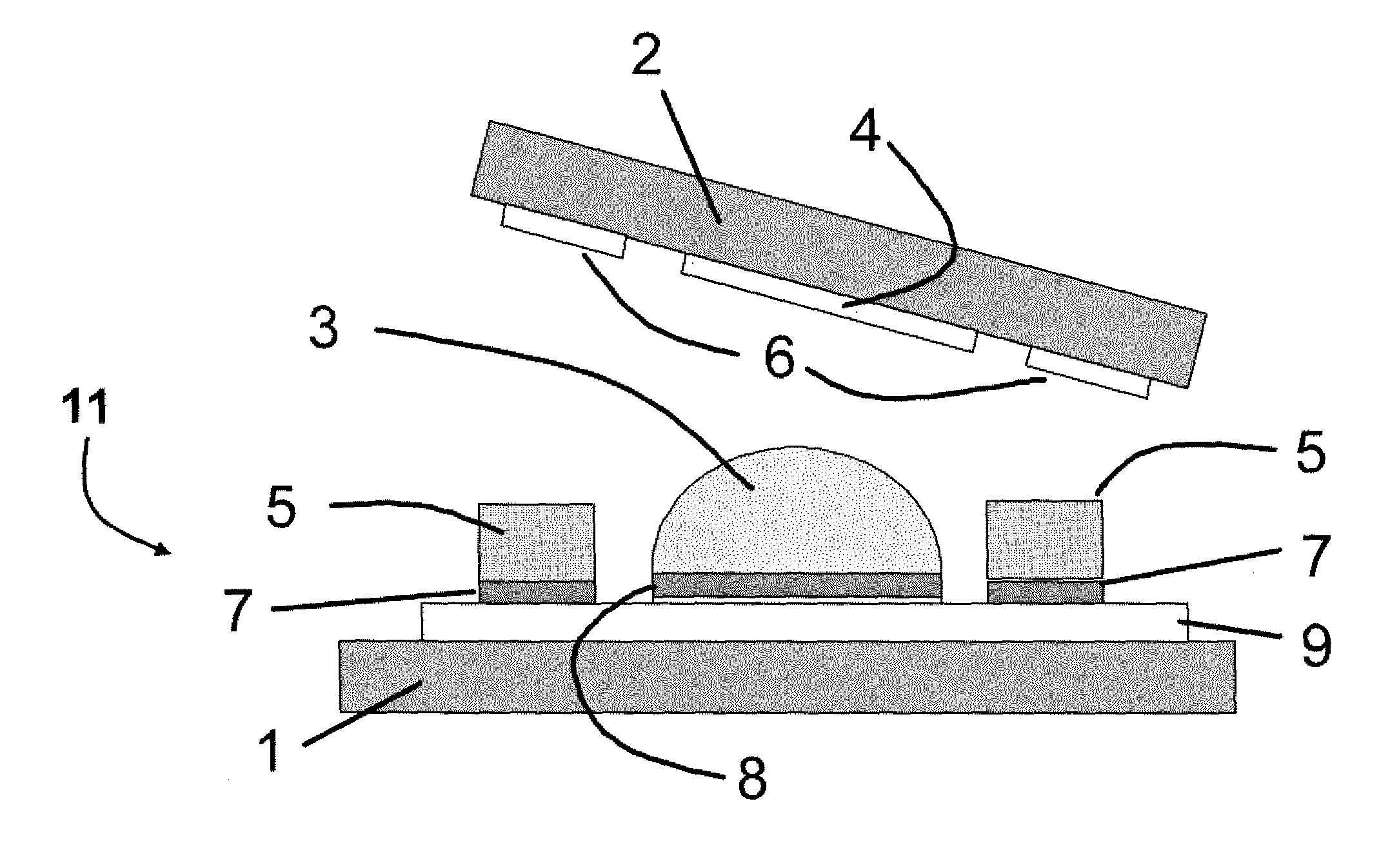
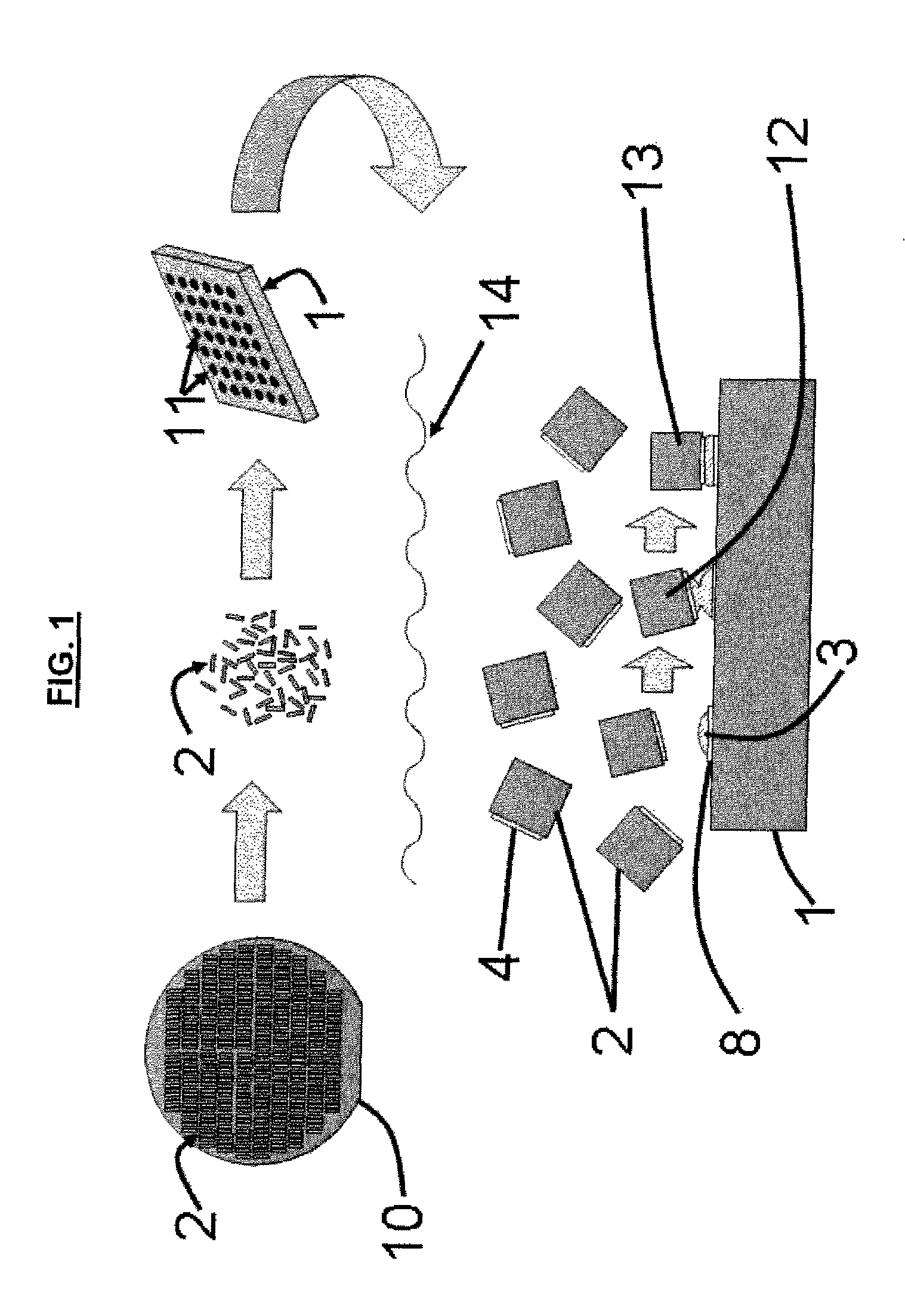
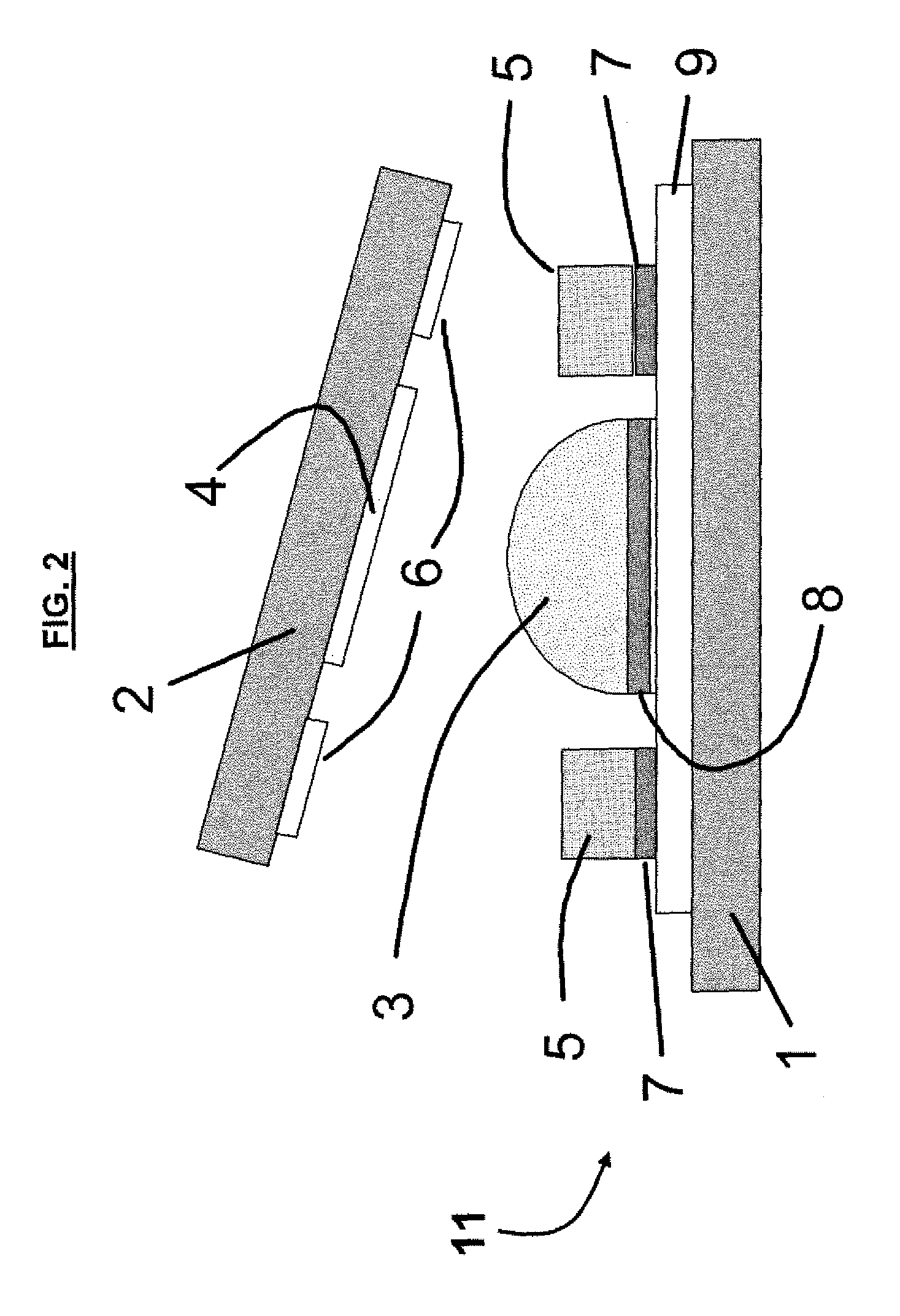
[0032]The embodiments herein provide a technique for forming electrical and mechanical connections via self-assembly without sacrificing the electrical qualities of those connections on microscale-sized parts (e.g., approximately 280 μm). The use of two alloys, or more generally the use of two ...


PUM

PropertyMeasurementUnit
sizeaaaaaaaaaa
sizeaaaaaaaaaa
diameteraaaaaaaaaa

Abstract

Self-assembling microscale electrical and mechanical connections includes a part binding site and a part electrical binding site; and a template binding site comprising a template electrical conductor layer; a metallization layer on the template electrical conductor layer; a bump structure comprising a solder alloy positioned on the metallization layer, wherein the solder alloy is liquefied to allow the bump structure to self-assemble and align with the part electrical binding site using capillary forces, and wherein the solder alloy only liquefies at a temperature above that at which the self-assembly and alignment is performed; and a fluid on the template electrical conductor layer, wherein the fluid comprises a melting point lower than that of the solder alloy, wherein the fluid binds with the part binding site.

Description

GOVERNMENT INTEREST[0001]The embodiments herein may be manufactured, used, and / or licensed by or for the United States Government without the payment of royalties thereon.BACKGROUND[0002]1. Technical Field[0003]The embodiments herein generally relate to microscale manufacturing techniques, and, more particularly, to microscale manufacturing techniques for electrical and mechanical connections.[0004]2. Description of the Related Art[0005]The assembly of devices from different materials and / or fabrication processes is a fundamental requirement of any modern system manufacturing procedure. Such assembly is often performed at the device level. For example, a printed circuit board is a system platform which electrically connects a number of individual devices, including resistors, capacitors, inductors, sensors, or integrated circuit (IC) chips. Each of these devices comes from a unique fabrication process, and each device size is constrained in part by the process used to assemble these...

Claims


Application Information

Patent Timeline
Patent Type & Authority Patents(United States)
IPC IPC(8): H01L21/44
CPCH01L24/95H05K3/3436H01L24/14Y02P70/613H05K3/3463H05K3/3494H05K2203/047H05K2203/0475H05K2203/048H05K2203/0776H01L2924/01006H01L2924/01023H01L2924/01033H01L2924/01322H01L2924/01327H01L2224/95145H01L2224/83192H01L2924/0132H01L2224/13111H01L2224/1412H01L2224/29111H01L2224/81192H01L2224/81234H01L2224/81815H01L2224/83815H01L2224/95085H01L2224/95101H01L2224/95146H01L2924/01082H01L2924/1461H01L2924/0105H01L2924/01083H01L2924/00015H01L2924/00H01L2924/14H01L2224/05573H01L2224/05568H01L2224/056H01L2924/00014H01L2224/0554Y02P70/50H01L2224/05599H01L2224/0555H01L2224/0556
Inventor MORRIS, CHRISTOPHER J.DUBEY, MANDAN
Owner UNITED STATES OF AMERICA THE AS REPRESENTED BY THE SEC OF THE ARMY
Why Eureka
Try Eureka