Bias-based linear high efficiency radio frequency amplifier

a radio frequency amplifier and bias-based technology, applied in amplifiers, amplifiers with semiconductor devices only, amplifiers with semiconductor devices, etc., can solve the problems of reducing battery capacity, reducing battery size, weight, or both, and increasing power consumption, so as to increase overall operating efficiency, reduce operating efficiencies, and increase operating efficiencies

Active Publication Date: 2012-11-27
QORVO US INC
View PDF13 Cites 0 Cited by
  • Summary
  • Abstract
  • Description
  • Claims
  • Application Information

AI Technical Summary

Benefits of technology

[0006]Class B amplifiers may have higher operating efficiencies than Class AB amplifiers; however, Class B amplifiers may not meet linearity requirements when operating at low output power levels. Conversely, Class AB amplifiers may meet linearity requirements at all output power levels, but may have reduced operating efficiencies, which may be particularly troublesome at high output power levels. Therefore, by transitioning between Class AB operation and Class B operation, linearity requirements may be met at all output power levels and overall operating efficiency may be increased when compared to continuous class AB operation. Peak current consumption, average current consumption, power dissipation, or any combination thereof may be reduced, which may extend battery life in portable wireless applications.
[0007]In some embodiments of the present disclosure, the RF power amplifier circuitry may include a source termination circuit, a load termination circuit, or both used in an unconventional manner to shape amplitude-based amplitude modulation (AM-AM) distortion, amplitude-based phase modulation (AM-PM) distortion, or both to extend a linear operating range of the RF power amplifier circuitry. Shaping AM-A...

Problems solved by technology

Support of such features may increase power consumption; however, market forces tend to drive down size and weight of portable wireless communications devices, thereby leading to redu...

Method used


Image

  • Bias-based linear high efficiency radio frequency amplifier
  • Bias-based linear high efficiency radio frequency amplifier
  • Bias-based linear high efficiency radio frequency amplifier

Examples


Embodiment Construction

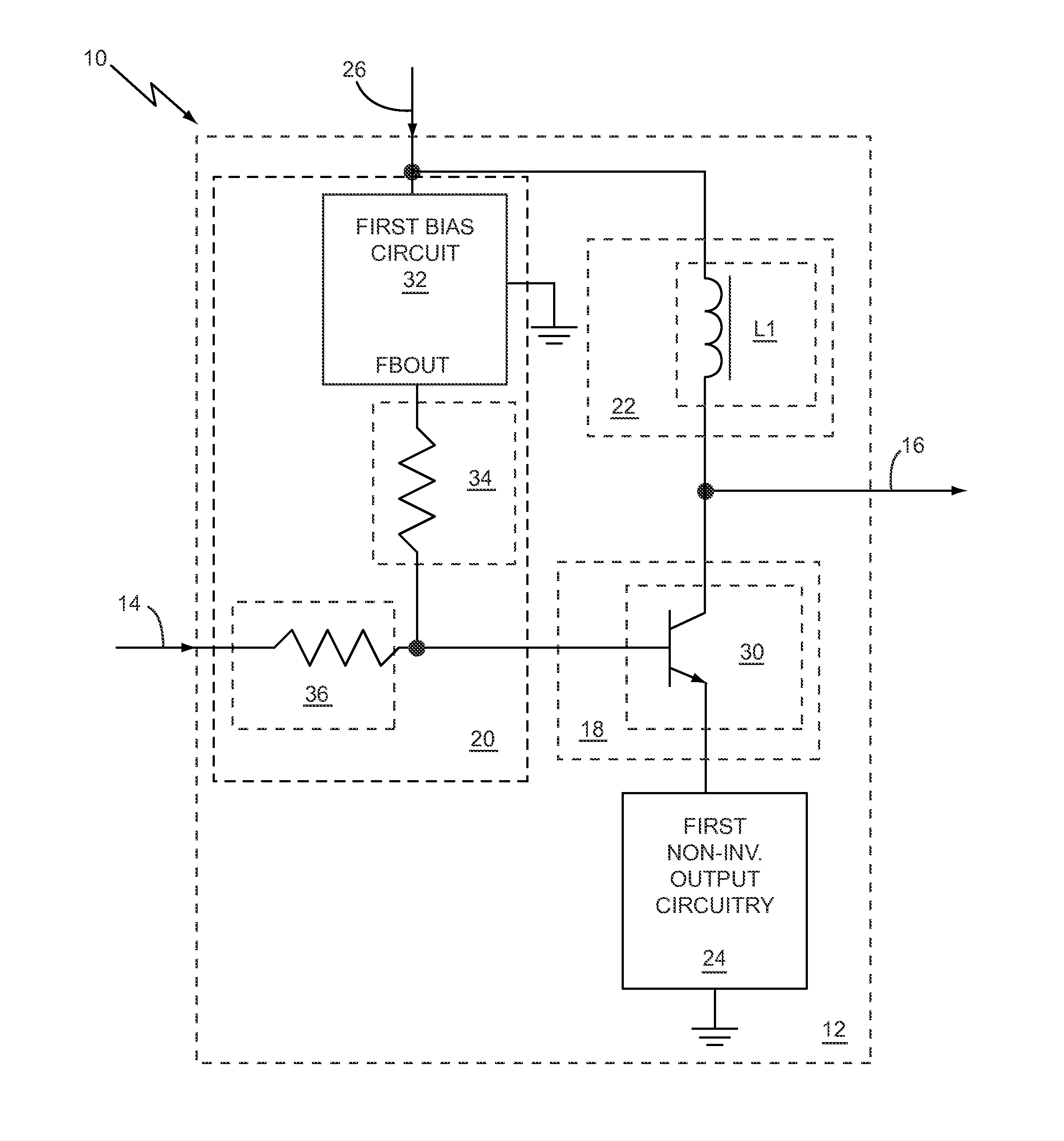
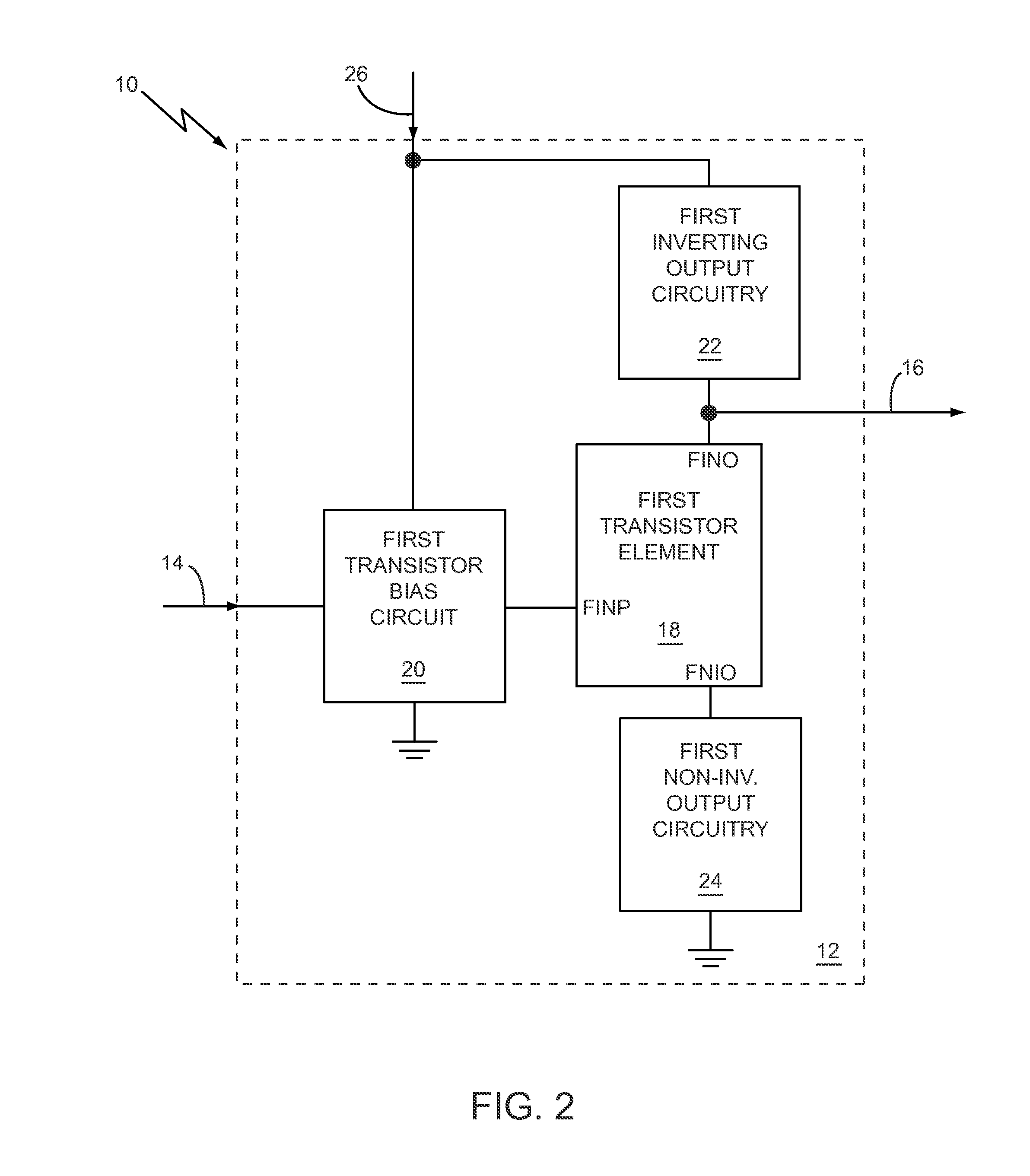
[0005]The present disclosure relates to RF power amplifier circuitry that may operate as either a Class AB amplifier or as a Class B amplifier based on a magnitude of RF output power provided by the RF power amplifier circuitry. A transistor bias circuit in the RF power amplifier circuitry may control transitioning between operating as the Class AB amplifier and operating as the Class B amplifier. When the magnitude of the RF output power is below a first threshold, the RF power amplifier circuitry may operate as a Class AB amplifier, and when the magnitude of the RF output power is above the first threshold, the RF power amplifier circuitry may operate as a Class B amplifier.

[0006]Class B amplifiers may have higher operating efficiencies than Class AB amplifiers; however, Class B amplifiers may not meet linearity requirements when operating at low output power levels. Conversely, Class AB amplifiers may meet linearity requirements at all output power levels, but may have reduced op...


PUM


Abstract

The present disclosure relates to RF power amplifier circuitry that may operate as either a Class AB amplifier or as a Class B amplifier based on a magnitude of RF output power provided by the RF power amplifier circuitry. A transistor bias circuit in the RF power amplifier circuitry may control transitioning between operating as the Class AB amplifier and operating as the Class B amplifier. When the magnitude of the RF output power is below a first threshold, the RF power amplifier circuitry may operate as a Class AB amplifier, and when the magnitude of the RF output power is above the first threshold, the RF power amplifier circuitry may operate as a Class B amplifier.

Description

[0001]This application claims the benefit of provisional patent application Ser. No. 61 / 105,226, filed Oct. 14, 2008, the disclosure of which is hereby incorporated herein by reference in its entirety.RELATED APPLICATIONS[0002]This application is related to U.S. patent application Ser. No. 12 / 579,117 entitled TERMINATION CIRCUIT BASED LINEAR HIGH EFFICIENCY RADIO FREQUENCY AMPLIFIER filed Oct. 14, 2009, now U.S. Pat. No. 8,072,271, which is concurrently filed herewith and incorporated herein by reference in its entirety.FIELD OF THE DISCLOSURE[0003]Embodiments of the present disclosure relate to radio frequency (RF) amplifiers, which may be used in RF communications circuits.BACKGROUND OF THE DISCLOSURE[0004]As wireless technology progresses, communications devices are becoming increasingly integrated and sophisticated. For example, smart phones are small, portable, battery-powered wireless communications devices that may support numerous applications and wireless communications pro...

Claims


Application Information

Patent Timeline
IPC IPC(8): H03F3/04
CPCH03F3/245H03F3/19H03F1/0272H03F2200/18
Inventor SPEARS, EDWARD T.STUTZMAN, JASON
Owner QORVO US INC
Why Eureka
Try Eureka