Controlled-unaided surge and purge suppressors for firearm muzzles

a suppressor and firearm technology, applied in the field of firearms, can solve the problems of less design guidance that can lead to the integration of suppressors, less science exists to explain how current designs can be modified or replaced to provide enhanced suppressor performance, and shorten the life cycle of suppressors. , to achieve the effect of reducing noise and muzzle flash, reducing noise, and reducing nois

Inactive Publication Date: 2012-12-04
FLODESIGN WIND TURBINE
View PDF12 Cites 24 Cited by
  • Summary
  • Abstract
  • Description
  • Claims
  • Application Information

AI Technical Summary

Benefits of technology

[0020]This new CUSPS approach attends to the blast surge effects by controlling the flow expansion into the suppressor, and attends to the flash effects by controlling inflow and outflow gas purging. The CUSPS suppressor rapidly reduces the pressure energy associated with a firearm muzzle blast before it exits the suppressor, thereby reducing noise and muzzle flash. The blast surge is mitigated through a rapid, divergent nozzle volume increase and thereafter through a series of vent holes strategically located around the suppressor outer wall. Applicants anticipate the noise frequency spectrum of the blast will be controllable through careful design of the hole contours, size and placement. The vent holes preferably converge towards the outside of the CUSPS. Alternatively, the holes could be contoured with divergent or convergent / divergent area distributions.
[0021]Following this, air is ingested inward through the same holes, mixed with the muzzle gases and purged axially through the exit port and vent holes. Preferably a two-stage supersonic mixer / ejector is used in the CUSPS suppressor to control or eliminate the Mach disk, while rapidly mixing and diluting the propellant with ambient air.
[0022]Based upon preliminary testing, Applicants believe that their CUSPS suppressor will generate the following benefits: lower noise; hide or eliminates flash; integrate cooling and self-cleaning; maintain firearm accuracy at longer distances, and lessen the amount of powder residue inside barrels.

Problems solved by technology

Existing suppression technology reduces noise and flash, but comparatively little science exists to explain how current designs can be modified or replaced to provide enhanced suppressor performance, including the useful life span of the suppressor.
Furthermore, even less design guidance exists that can lead to integration of suppressors into a firearm's barrel assembly.
Lessons learned as a result of the ongoing military and homeland security based conflicts have indicated that increased use of current suppressors, as part of everyday operations, have led to shortened life cycles of suppressors, increased maintenance (and sometimes damage) of weapons, and considerable variability in weapon accuracy.
Both of these blasts are sources of low frequency noise that carry very far distances.
The over-expanded gas results in the normal shock or Mach disk, which causes the secondary flash and a significant portion of the noise.
Gas turbine technology has yet to be applied successfully to firearm muzzle suppressors.

Method used


Image

  • Controlled-unaided surge and purge suppressors for firearm muzzles
  • Controlled-unaided surge and purge suppressors for firearm muzzles
  • Controlled-unaided surge and purge suppressors for firearm muzzles

Examples


Embodiment Construction

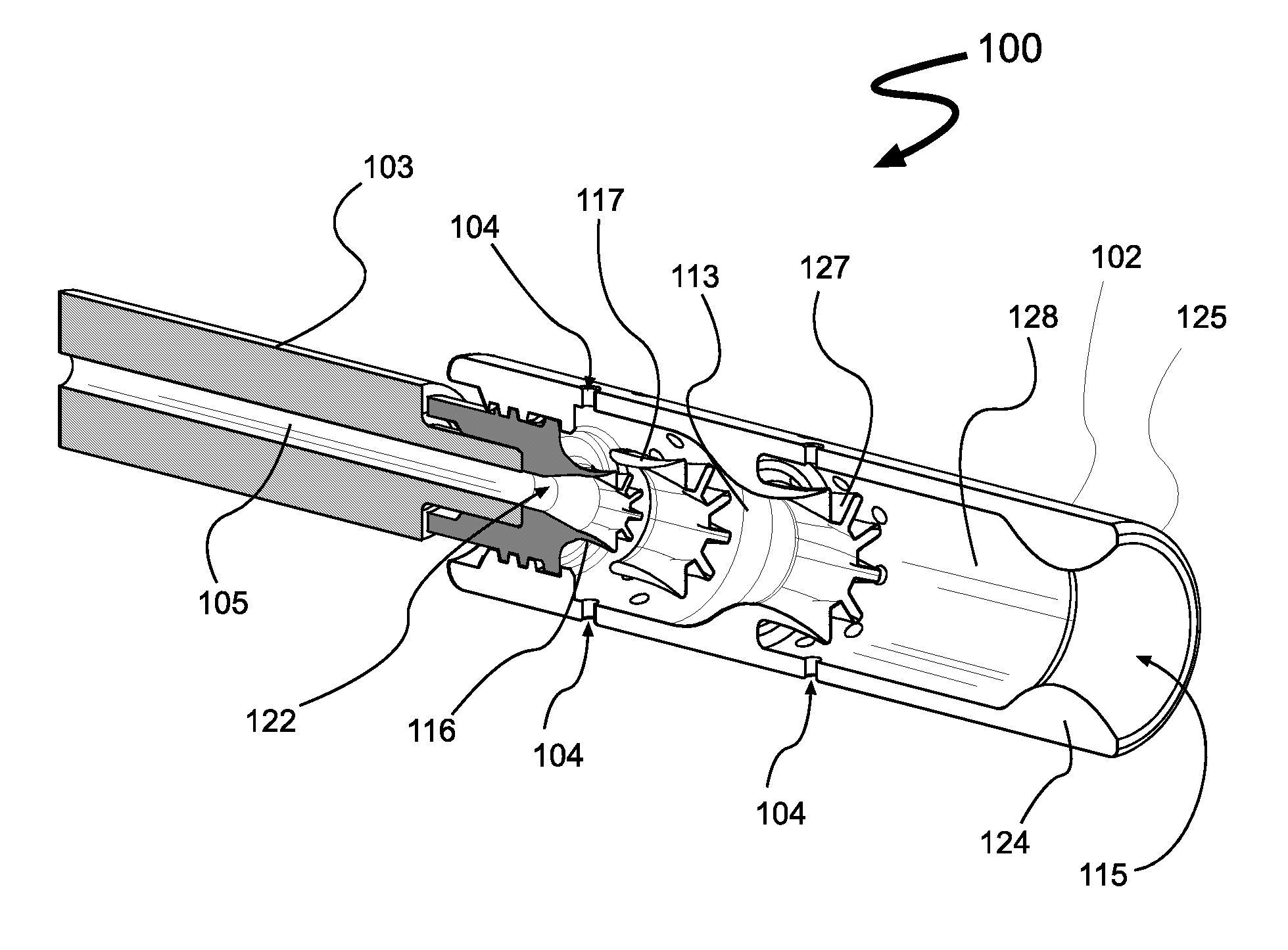
[0039]Referring to the drawings in detail, FIGS. 2A-10A show alternate embodiments of Applicants CUSPS suppressor for firearms. Like elements in the drawings use the same element numbers.

[0040]In the preferred embodiment 100 (see FIG. 8A), the CUSPS is a detachable firearm suppressor comprising:[0041]a. a tubular housing 102, removably affixed to and axially aligned with the muzzle end of a firearm barrel 103, wherein the housing 102 has vent openings 104 radially and longitudinally distributed in its outer surface or wall, and the housing 102 contains:[0042]i. a projectile entrance port 105, adjacent the terminus, that allows the blast wave and exit gas from a discharged firearm to expand inside the housing 102;[0043]ii. a projectile exit port 114 and internal support structure at its terminus, wherein the preferred exit port is an exit hole 115 in the housing which is significantly larger than the bore (i.e. hole) 105 of the barrel 103; and[0044]iii. a one-stage mixer / ejector in a...


PUM


Abstract

A Controlled Unaided Surge and Purge (CUSPS) suppressor for firearms uses the blast and plume characteristics inherent to the ballistic discharge process to develop a new two-step controlled surge and purge system centered around advanced mixer-ejector concepts. The blast surge noise is reduced by controlling the flow expansion, and the flash effects are reduced by controlling inflow and outflow gas purges. In the preferred embodiment, suppressor vent holes are convergently contoured to better reduce the blast surge. Preferably a two-stage supersonic mixer / ejector system, in combination with adjacent vent holes in the suppressor housing and a divergent entrance nozzle, is used to control or eliminate the external Mach disk, while rapidly mixing and diluting the propellant with purged gases. A diffuser downstream of the mixer / ejector system further increases ejector performance and pumping. The pumped gases are used to self-clean and cool the CUSPS suppressor.

Description

RELATED APPLICATION[0001]This application claims priority from Applicants' U.S. Provisional Patent Application, Ser. No. 60 / 994,280, filed Sep. 18, 2007 (hereinafter “Applicants' Provisional Application”). Applicants hereby incorporate the disclosure of Applicants' Provisional Application by reference.FIELD OF INVENTION[0002]The present invention deals generally with firearms. More particularly, it deals with noise and flash suppressors for firearm muzzles.BACKGROUND OF INVENTION[0003]Reducing muzzle noise and flash from military and security personnel firearms (e.g., long guns and pistols) provide a significant tactical advantage in the field. Existing suppression technology reduces noise and flash, but comparatively little science exists to explain how current designs can be modified or replaced to provide enhanced suppressor performance, including the useful life span of the suppressor. Furthermore, even less design guidance exists that can lead to integration of suppressors into...

Claims


Application Information

Patent Timeline
Patent Type & Authority Patents(United States)
IPC IPC(8): F41A21/30
CPCF41A21/34
Inventor PRESZ, JR., WALTER M.WERLE, MICHAEL J.LIPKENS, BART
Owner FLODESIGN WIND TURBINE
Why Eureka
Try Eureka