
Arrangement for and method of two dimensional and three dimensional precision location and orientation determination

a two-dimensional and three-dimensional precision and positioning technology, applied in wave based measurement systems, navigation instruments, instruments, etc., can solve the problems that filtering techniques and averaging techniques that are effectively removing gaussian noise will not work effectively on offsetted signals, and achieve the effect of improving at least one of position and orientation calculations

Active Publication Date: 2012-12-04
TOMTOM GLOBAL CONTENT
View PDF16 Cites 24 Cited by
  • Summary
  • Abstract
  • Description
  • Claims
  • Application Information

AI Technical Summary

Benefits of technology

The present invention provides a system and method for accurately determining position and orientation of a moving vehicle along a trajectory. It uses GPS samples collected from the vehicle and eliminates inaccurate GPS samples in a non-linear way, resulting in a highly accurate position and orientation calculation. The invention can be used in an off-line environment where position / orientation measurements are computed from data collected with a vehicle that has been driven along a road in a smooth way. It also provides the option of calculating the drift in output signals of an IMU used to calculate the position and orientation of the vehicle and correcting it for the drift. The invention can be cost-effectively implemented and used in an off-line environment to produce a more sensitive determination of the trajectory and a slightly more accurate final result.

Problems solved by technology

However, some filtering techniques and averaging techniques that are effectively removing Gaussian noise will work ineffectively on offsetted signals that show long time constant shifts to series of measurements, as in GPS measurements.

Method used


Image

  • Arrangement for and method of two dimensional and three dimensional precision location and orientation determination
  • Arrangement for and method of two dimensional and three dimensional precision location and orientation determination
  • Arrangement for and method of two dimensional and three dimensional precision location and orientation determination

Examples


Embodiment Construction

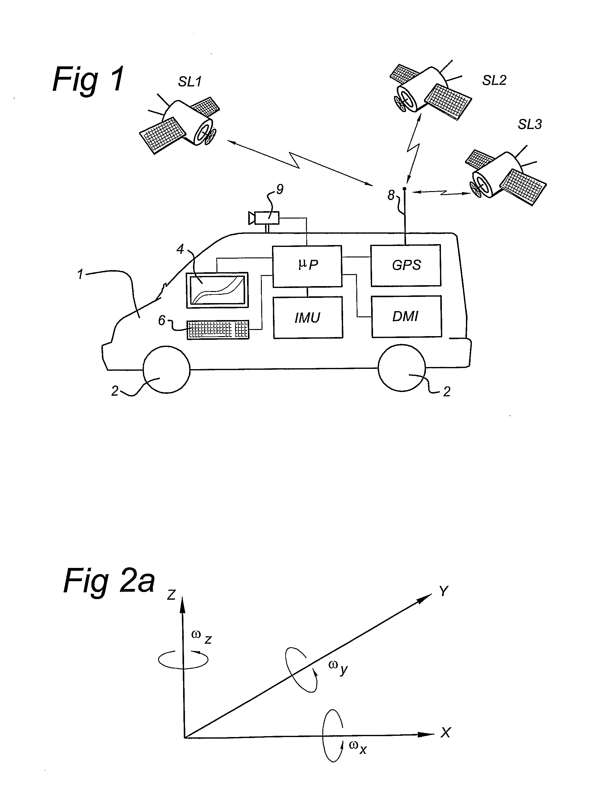
[0030]FIG. 1 shows a vehicle provided with an existing high accuracy position determination device. FIG. 1 shows a vehicle 1, provided with a plurality of wheels 2. Moreover, the vehicle 1 is provided with a high accuracy position determination device. As shown in FIG. 1, the position determination device comprises the following components:[0031]a GPS (global positioning system) unit connected to an antenna 8 and arranged to communicate with a plurality of satellites SLi (i=1, 2, 3, . . . ) and to calculate a position signal from signals received from the satellites SLi. The GPS system also delivers heading data (i.e., direction of travel) and speed of the vehicle 1. The GPS system may be a DGPS system (differential GPS) providing an accuracy of 1 sigma / 1 meter (apart from possible white noise). The GPS system is connected to a microprocessor μP that is arranged to process the GPS output signals.[0032]a DMI (Distance Measurement Instrument). This instrument is an odometer that measu...


PUM


Abstract

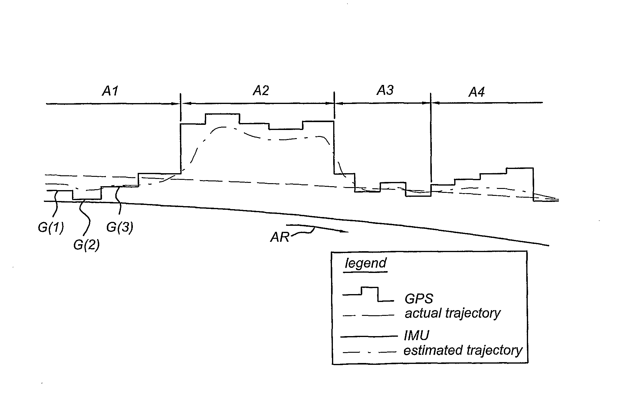
In one embodiment of the present invention, a method of and apparatus for determining inaccurate GPS samples in a set of GPS samples is disclosed, according to the following actions: a) obtaining GPS samples as taken by a global positioning system on board a vehicle when traveling along a trajectory; b) obtaining a first estimation of the trajectory based on the GPS samples; c) obtaining a second estimation of the trajectory at least based on measurements made by an inertial measurement unit on board vehicle when traveling along the trajectory; d) comparing the first and second estimations; e) establishing locations where the first estimation shows a variation compared with the second estimation above a predetermined threshold; f) if no such locations can be established continue with action j), otherwise continue with action g); g) removing GPS samples associated with the locations of high variation as being inaccurate GPS samples, thus forming a set of remaining GPS samples; h) calculating the first estimation anew of the trajectory based on the remaining GPS samples and calculating the second estimation anew; i) repeating actions d) to h); j) ending the actions.

Description

FIELD OF THE INVENTION[0001]The present invention relates to an arrangement for and a method of two dimensional and three dimensional precision location and orientation determination.PRIOR ART[0002]Position determination devices are known from the prior art. Nowadays they are increasingly applied in, for instance, vehicles such as vehicles, ships and aircraft. To that effect, such a vehicle may comprise different measurement units like a GPS (Global Positioning System), an IMU (inertial Measurement Unit and a DMI (Distance Measurement Instrument).[0003]While travelling, output data of such measurement units is used by a processor to calculate a position and / or orientation of the vehicle. Depending on the application, the measurements made by these measurement units are used on-line or off-line.[0004]It is a general desire to provide as accurate as possible location and orientation measurement from the 3 measurement units: GPS, IMU and DMI. Many problems should be solved to that effe...

Claims


Application Information

Patent Timeline
Patent Type & Authority Patents(United States)
IPC IPC(8): G01S1/00G01S5/02G01S5/14G01S19/23G01S19/47
CPCG01C21/165G01C21/28G01S19/23G01S19/47G01C21/1656
Inventor KMIECIK, MARCIN MICHALMIKSA, KRZYSZTOF
Owner TOMTOM GLOBAL CONTENT
Learn More