Aeroengine drain assembly

a technology of aeroengine and assembly, which is applied in the direction of liquid fuel engines, machines/engines, launching weapons, etc., can solve the problems of aerodynamic loss and weight of power plants, particularly large distance between engines and external surfaces of nacelles, etc., and achieve the effect of more aerodynamics

Active Publication Date: 2012-12-11
ROLLS ROYCE PLC
View PDF4 Cites 11 Cited by
  • Summary
  • Abstract
  • Description
  • Claims
  • Application Information

AI Technical Summary

Benefits of technology

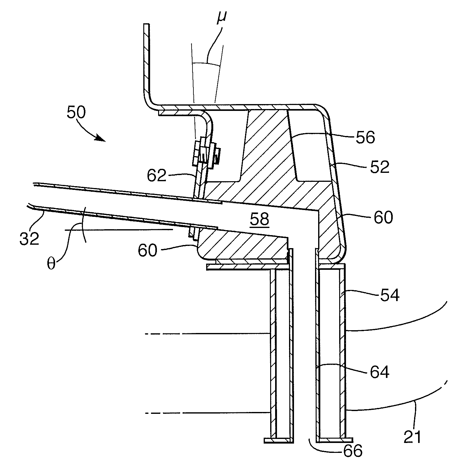
[0005]Therefore, it is an object of the present invention to provide a more compact drains assembly and therefore a more aerodynamic and lighter nacelle.

Problems solved by technology

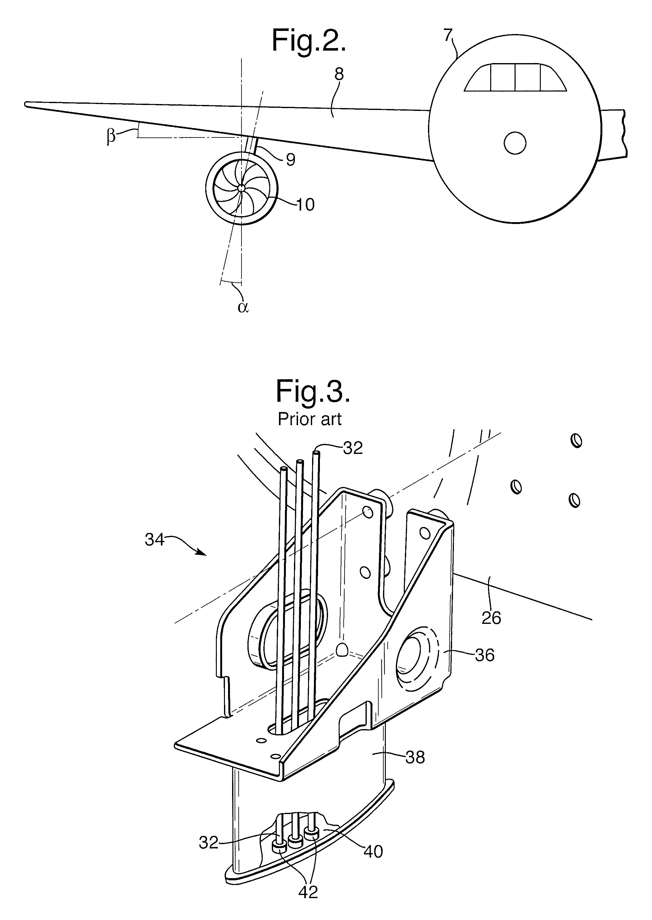
Although a working design, this conventional arrangement means that the distance between the engine and the external surface of the nacelle is particularly large and the powerplant is therefore disadvantaged by aerodynamic losses and weight.

Method used


Image

  • Aeroengine drain assembly
  • Aeroengine drain assembly
  • Aeroengine drain assembly

Examples


Embodiment Construction

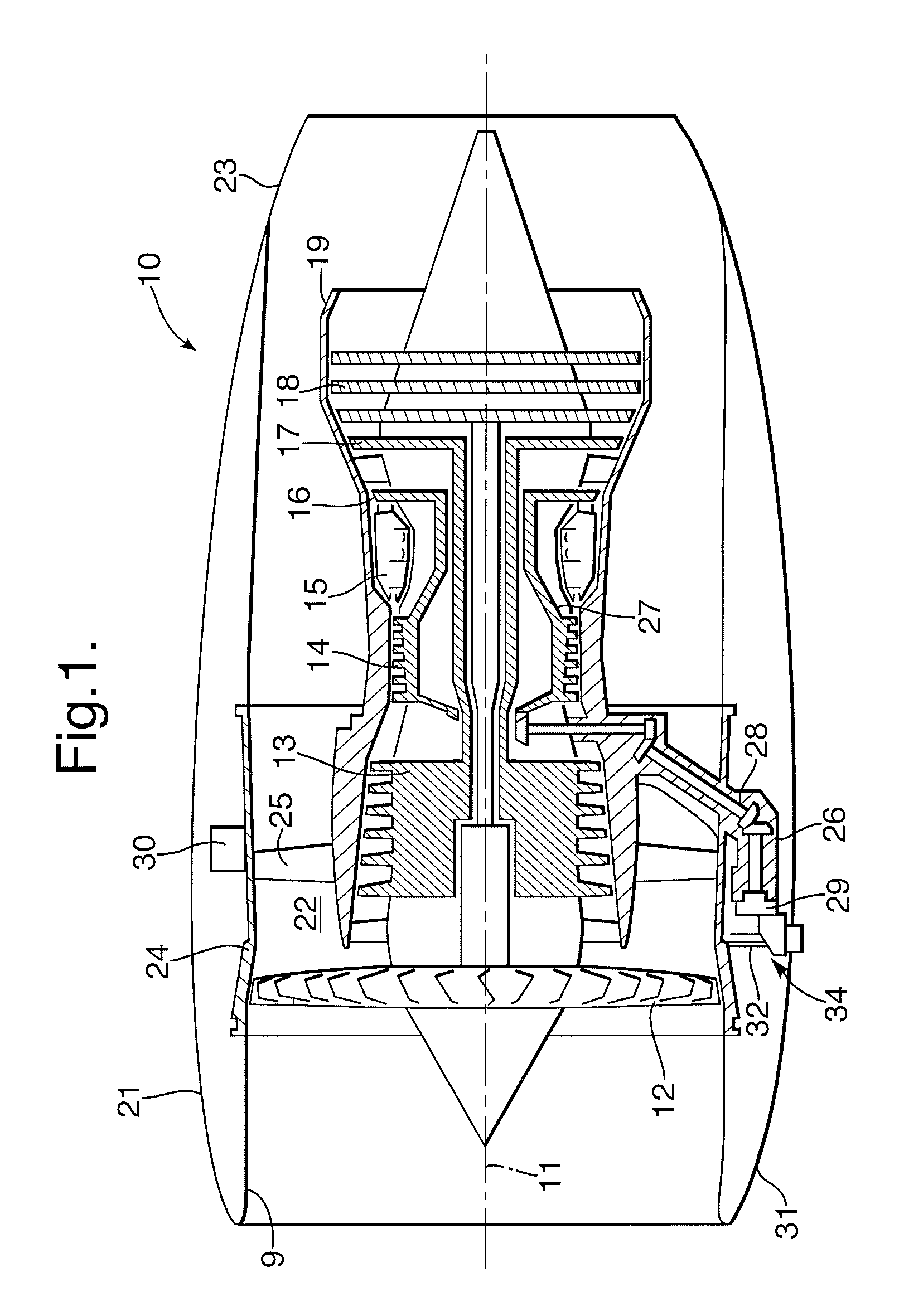
[0020]Referring to FIG. 1, a ducted fan gas turbine engine generally indicated at 10 has a principal and rotational axis 11. The engine 10 comprises, in axial flow series, an air intake 9, a propulsive fan 12, an intermediate pressure compressor 13, a high-pressure compressor 14, combustion equipment 15, a high-pressure turbine 16, and intermediate pressure turbine 17, a low-pressure turbine 18 and a core exhaust nozzle 19. A nacelle 21 generally surrounds the engine 10 and defines the intake 9, a bypass duct 22 and an exhaust nozzle 23.

[0021]The gas turbine engine 10 works in the conventional manner so that air entering the intake 9 is accelerated by the fan 12 to produce two air flows: a first airflow into the intermediate pressure compressor 13 and a second airflow which passes through a bypass duct 22 to provide propulsive thrust. The intermediate pressure compressor 13 compresses the airflow directed into it before delivering that air to the high pressure compressor 14 where fu...


PUM

PropertyMeasurementUnit
mounting angleaaaaaaaaaa
angleaaaaaaaaaa
dihedral angleaaaaaaaaaa

Abstract

A gas turbine engine has a nacelle, a plurality of pipes and a drains assembly, the drains assembly including a drains mast that extends through the nacelle and provides an outlet for the pipes. The engine is characterised in that drains assembly has a connection block defining internal passages and is arranged to connect between the pipes and the drains mast. The connection block also has lateral connections to the pipes enabling the nacelle to have a lower profile; thereby reducing aerodynamic drag.

Description

CROSS-REFERENCE TO RELATED APPLICATION[0001]This application is entitled to the benefit of British Patent Application No. GB 0701683.5 filed on Jan. 30, 2007.FIELD OF THE INVENTION[0002]The present invention relates to a drain assembly for discharging fluids from pipes and conduits of a gas turbine engine.BACKGROUND OF THE INVENTION[0003]A gas turbine engine requires a drain assembly to collect excess or spilled fluids from various service pipes and to discharge the fluids safely overboard. The drain assembly comprises a drains mast that extends through a nacelle surrounding the engine. Identification markings are placed on the mast to indicate particular fluid spill and therefore assist engine fault diagnosis.[0004]Drain assemblies must be positioned at or near to the bottom dead centre of the engine to allow the spilled fluids to exit the drains mast via gravity. Conventional engine drain assemblies, as shown in FIG. 3, comprise a mounting bracket off which the mast extends, the p...

Claims


Application Information

Patent Timeline
Patent Type & Authority Patents(United States)
IPC IPC(8): F01D25/24F01D25/32
CPCB64D29/00F02C7/00F05D2300/431F05D2260/602F02C7/32
Inventor RUSSELL, MICHAEL EDWIN
Owner ROLLS ROYCE PLC
Why Eureka
Try Eureka