Femoral gauge

a femoral gauge and femoral tube technology, applied in the field of hip surgery, can solve the problems of shortening the recovery time of patients, presenting challenges to surgeons, operating in the confines of a small incision, etc., and achieve the effect of reducing the risk of impingemen

Active Publication Date: 2012-12-11
MICROPORT ORTHOPEDICS HLDG INC
View PDF15 Cites 6 Cited by
  • Summary
  • Abstract
  • Description
  • Claims
  • Application Information

AI Technical Summary

Benefits of technology

[0019]A method is provided for locating and removing osteophytes or structural abnormalities on a natural femoral head and neck junction in order to optimize offset between a femoral head implant and the natural neck and thereby minimize the risk of impingement between the natural femoral neck and an acetabular implant, the method comprising: providing a set of femoral gauges of the type described herein, exposing a proximal aspect of the femur, selecting from the set of femoral gauges a gauge that best fits a superior aspect of a natural femoral head of the femur, rotating the selected femoral gauge around a juncture of the natural femoral head and the natural femoral neck to thereby locate areas of potential impingement between the natural femoral neck and an acetabular implant, and removing the areas of impingement until the femoral gauge can be rotated around the juncture of the natural femoral head and the natural femoral neck without lifting off of the natural femoral head. After a femoral head implant has been secured on the natural femoral neck, the selected femoral gauge can be rotated around a juncture of the femoral head implant and the natural femoral neck to thereby locate areas of potential impingement between the natural femoral head and an acetabular implant. If there are any areas of impingement, the areas of impingement can be removed until the femoral gauge can be rotated around the juncture of the femoral head implant and the natural neck without lifting off of the femoral head implant.

Problems solved by technology

MIS procedures may reduce trauma to the patient's muscles and other tissues, and typically result in shorter patient recovery time.
However, operating in the confines of a small incision presents challenges to the surgeon.

Method used


Image

  • Femoral gauge
  • Femoral gauge
  • Femoral gauge

Examples


Embodiment Construction

[0029]In the following detailed description of the preferred embodiments, reference is made to the accompanying drawings which form a part hereof, and in which are shown by way of illustration specific embodiments in which the invention may be practiced. It is to be understood that other embodiments may be utilized and structural changes may be made without departing from the scope of the present invention.

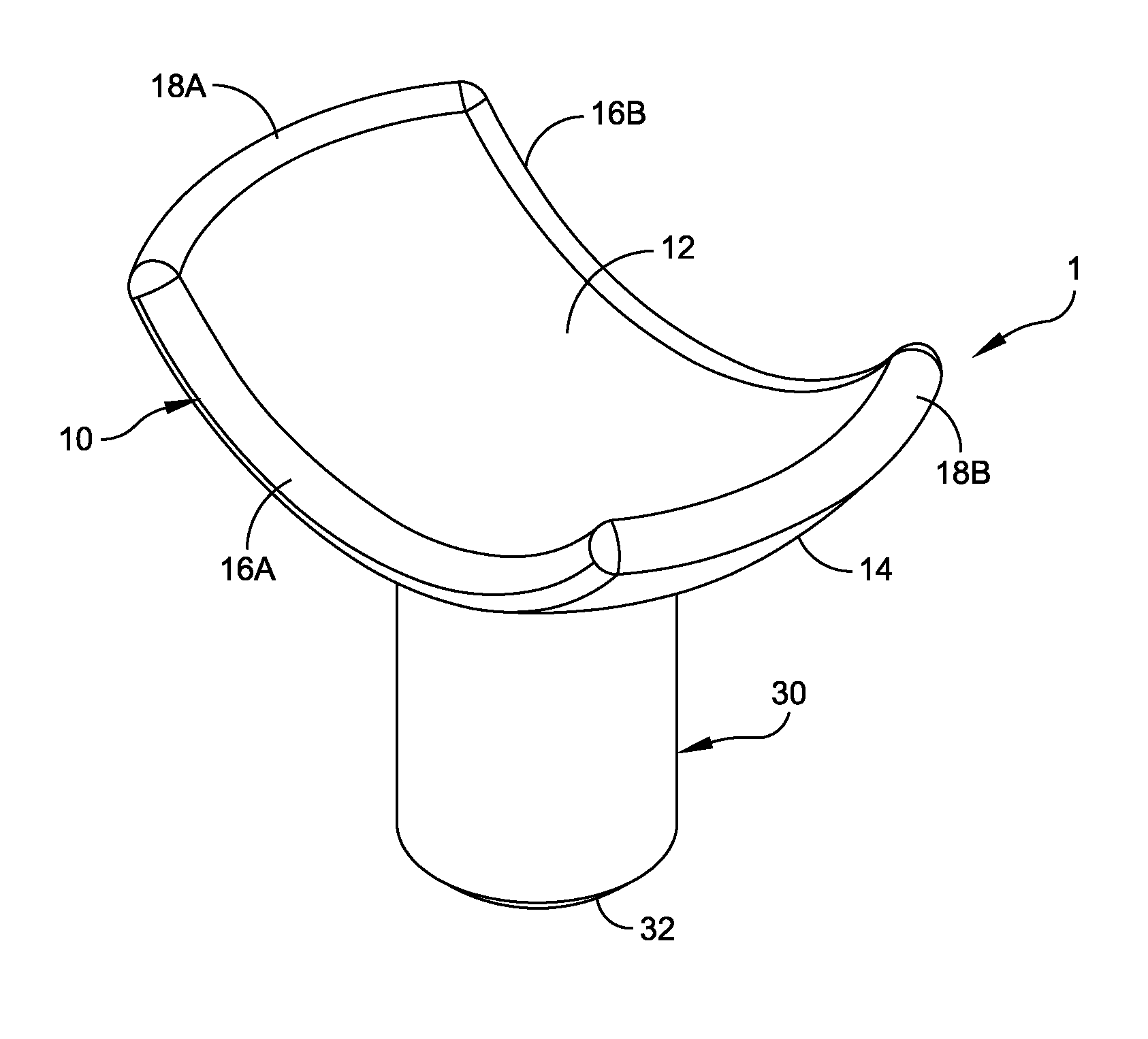
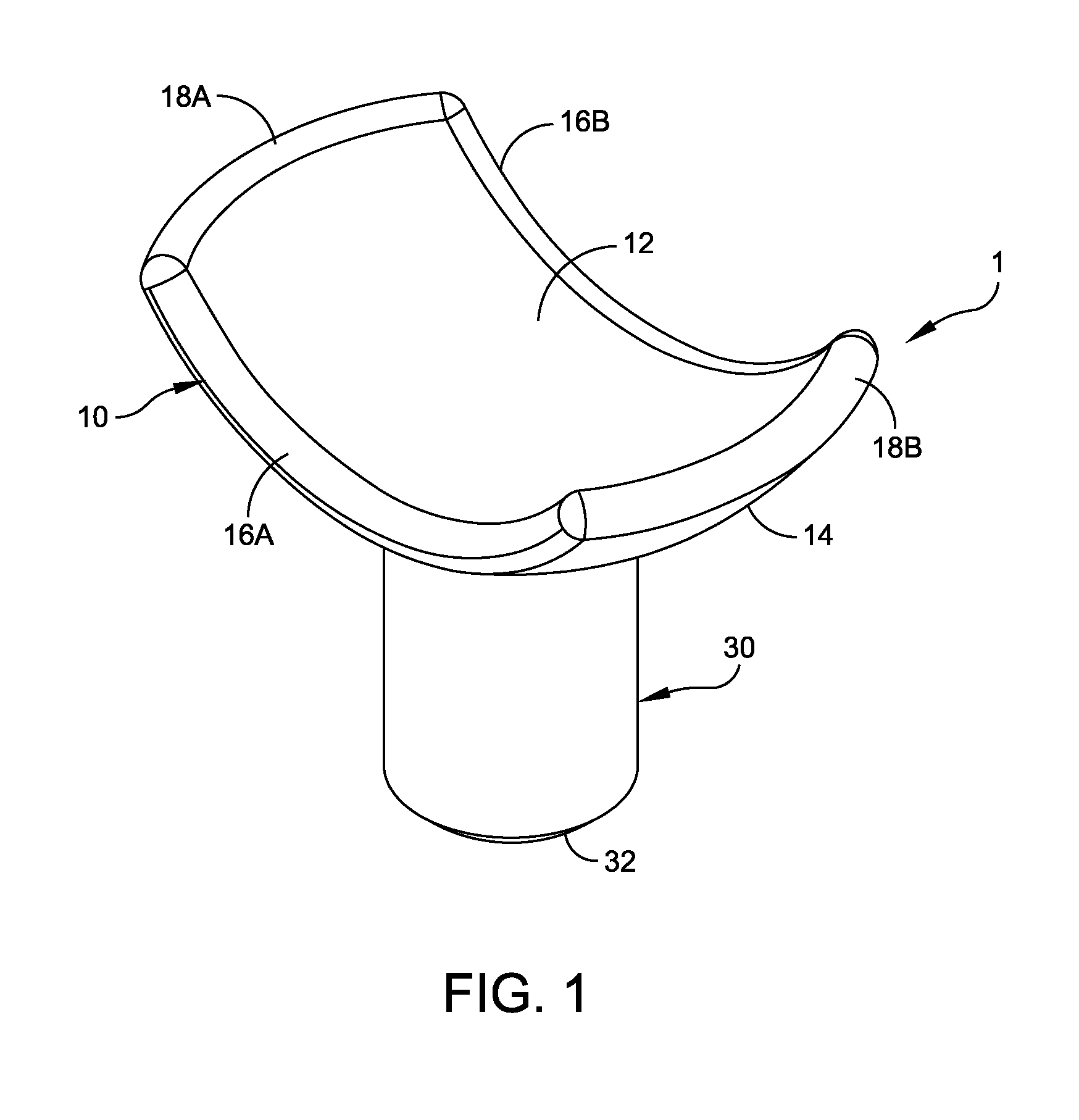
[0030]As shown in FIG. 1, the invention includes a femoral gauge 1 for use during surgical intervention on the hip, both for joint preservation and hip resurfacing arthroplasty. As will be described in further detail below, the femoral gauge 1 is used to select an appropriately sized femoral head implant 200. The femoral gauge 1 can also be used to locate osteophytes or other structural abnormalities 108 on a natural femoral head and neck.

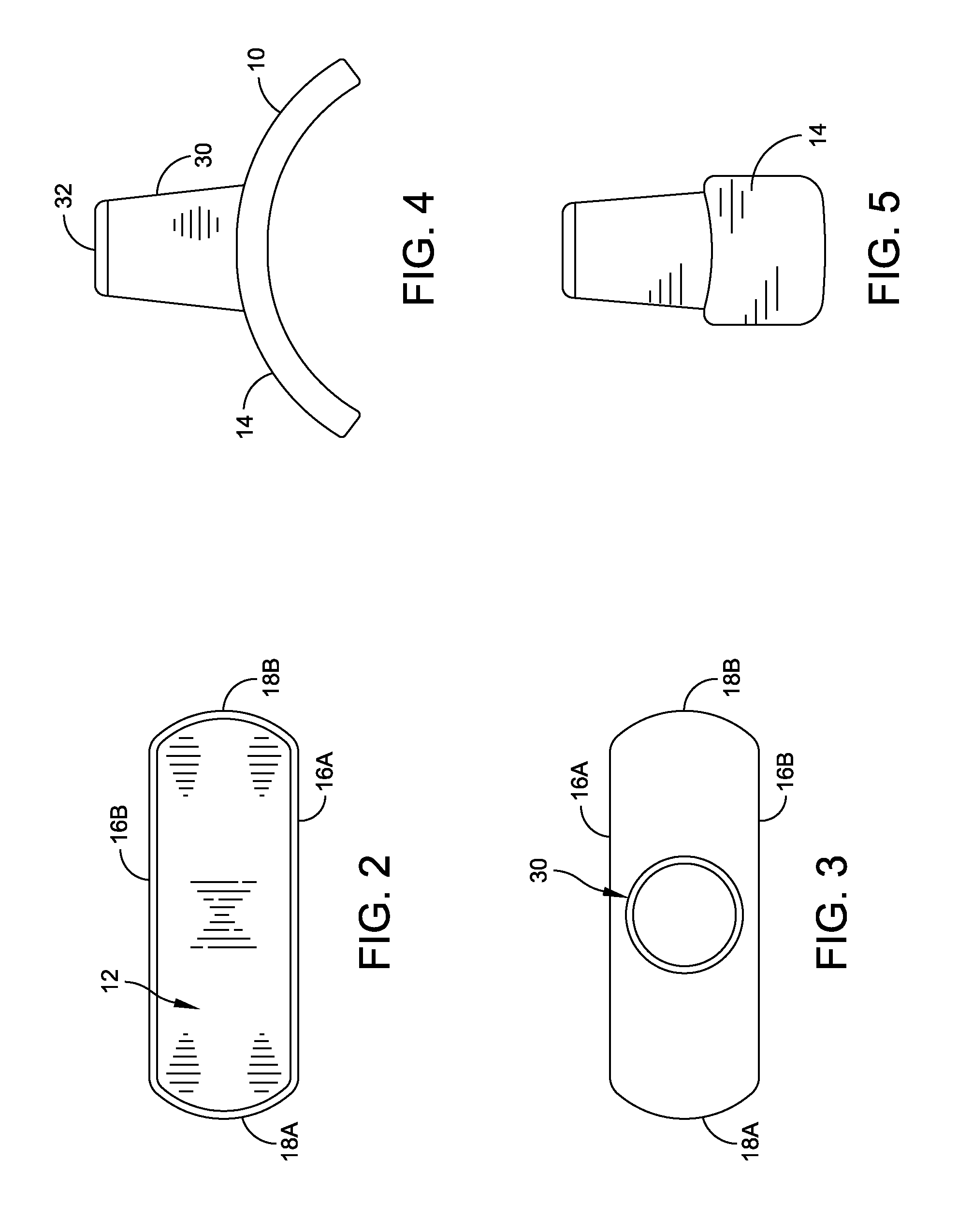
[0031]As shown in FIG. 1, the femoral gauge 1 includes a gauge portion 10. The gauge portion 10 has a concave gauge surface 12 and an opposing b...


PUM


Abstract

A femoral gauge for sizing a femoral head implant and locating osteophytes or structural abnormalities comprising a gauge portion, the gauge portion having a concave gauge surface and an opposing back surface, the gauge surface defined by a pair of opposing lengthwise sides and a pair of widthwise sides, the gauge surface having a substantially spherical contour, the spherical contour sized for selection of a correspondingly sized femoral head implant, and a handle portion extending from the gauge portion, the handle portion positioned and configured for use in positioning the gauge surface. A plurality of different sized gauges can be provided. Areas of potential infringement can be located by rotating the femoral gauge around the juncture of the natural or implant femoral head and the natural femoral neck. Areas of impingement are removed until the femoral gauge can be rotated around the juncture without lifting off of the femoral head.

Description

CROSS REFERENCE TO RELATED APPLICATIONS[0001]This application is a continuation of and claims priority to U.S. Provisional Patent Application Ser. No. 60 / 700,828, filed Jul. 20, 2005.STATEMENT REGARDING FEDERALLY SPONSORED RESEARCH OR DEVELOPMENT[0002]Not applicableREFERENCE TO A MICROFICHE APPENDIX[0003]Not applicableFIELD OF THE INVENTION[0004]The present invention relates to hip surgery, and more particularly to instruments for use in sizing femoral head implants for use in conservative intra-articular hip procedures.BACKGROUND OF THE INVENTION[0005]In recent years, efforts have been made to develop instruments and procedures for use in minimally invasive hip arthroplasty procedures. In minimally invasive surgical (“MIS”) procedures, the operation is carried out through a small incision, such as an 8 cm incision. MIS procedures may reduce trauma to the patient's muscles and other tissues, and typically result in shorter patient recovery time. However, operating in the confines of...

Claims


Application Information

Patent Timeline
Patent Type & Authority Patents(United States)
IPC IPC(8): G01B1/00
CPCA61F2/4657A61F2/3601A61F2/3603A61F2002/3009A61F2002/30245A61F2002/3025A61F2002/30616A61F2002/3611A61F2002/4659A61F2230/0071A61F2250/0091A61F2002/30242A61F2002/30593
Inventor BEAULE, PAUL E.
Owner MICROPORT ORTHOPEDICS HLDG INC
Why Eureka
Try Eureka