Wash process for removing undesired components in samples being analyzed

a technology of undesired components and wash process, which is applied in the direction of material analysis, instruments, and withdrawal sample devices, can solve the problems of significant adverse effects on performance, contaminated outer surface of aspirating nozzles with wash fluid containing unbound materials, and large erroneous signals, so as to reduce the amount of signal from the bound fraction

Inactive Publication Date: 2012-12-11
ORTHO-CLINICAL DIAGNOSTICS
View PDF29 Cites 22 Cited by
  • Summary
  • Abstract
  • Description
  • Claims
  • Application Information

AI Technical Summary

Benefits of technology

[0048]As the plot in FIG. 4 demonstrates, if the line approaches horizontal one will be working with less signal and therefore have inherently more imprecision. If one were to employ a wash method that produced a more precise signal response but did this at the expense of reducing half of the usable signal in the critical range, then there would be little or no benefit unless the improvement is significantly better than 2×. An advantage of the present invention that there is a significant improvement in low end precision without reducing the amount of usable signal. This aspect of the invention is useful in any analysis that may have an interfering undersired component on the surface of the sample holder, such as a well or cuvette described above. The timing of the surface film removal depends on the system and chemistry being employed. If immunochemistry were employed, the removal would be after addition of signal reagent and any incubation. This incubation is expected to enhance the amount of material that becomes dislodged from the surface. It may also impact the amount of material that floats to the surface. It would be expected that the effectiveness of this process is greatest after some incubation period. Chemiluminescent (immunochemistry) assays will have this incubation period and not produce a buildup of signal since this type of process only produces light.
[0049]An advantage of the surface removal embodiment (hereinafter also referred to as the aspirate or aspiration embodiment) that employs an incubation of a signal producing reagent is that it enables an overall shorter time to result and better system throughput for the equivalent amount of wash efficiency. This is because the aspirate embodiment makes double use of the signal reagent incubation by turning signal reagent incubation into a supplemental wash process (soak) while incubating at the same time. For example, in a preferred embodiment described above, there is generally a total of 120 seconds of soak time between washes (3 soaks at 40 seconds each). With the preferred aspiration process, an additional soak time of 4 minutes and 40 seconds is added (i.e., the signal incubation time in certain embodiments) is provided resulting in a greater than 4 times increase for soak time. Thus, there is a longer effective wash / soak time for the embodiments that use the aspiration process compared to an equivalent method but does not employ the aspiration process.
[0050]If the analysis is a calorimetric analysis having a dye detection system, the surface film or layer should be removed before the endpoint color is measured. A dye detection system results in a buildup of color density with time if there is signal producing material present. Thus, if the aspirate embodiment is used in a calorimetric type assay the method will be somewhat modified. For example, the surface of the fluid may be aspirated multiple times during the detection incubation process. Another alternative would be to put in a wash fluid and aspirate the surface after an incubation time. An advantage of this method over the current state of the art methods having an extended wash soak time is that aspiration of the surface film before removal of the bulk fluid would be expected to remove a concentrated layer of unbound material. This unbound material could get re-deposited on the surface of the container using conventional aspiration methods where an aspiration nozzle removes the bulk fluid without first selectively removing or aspirating the surface film.
[0051]The ultimate timing of the surface film removal depends on the system and chemistry being employed and can be determined by those skilled in the art using the present specification as a guide.
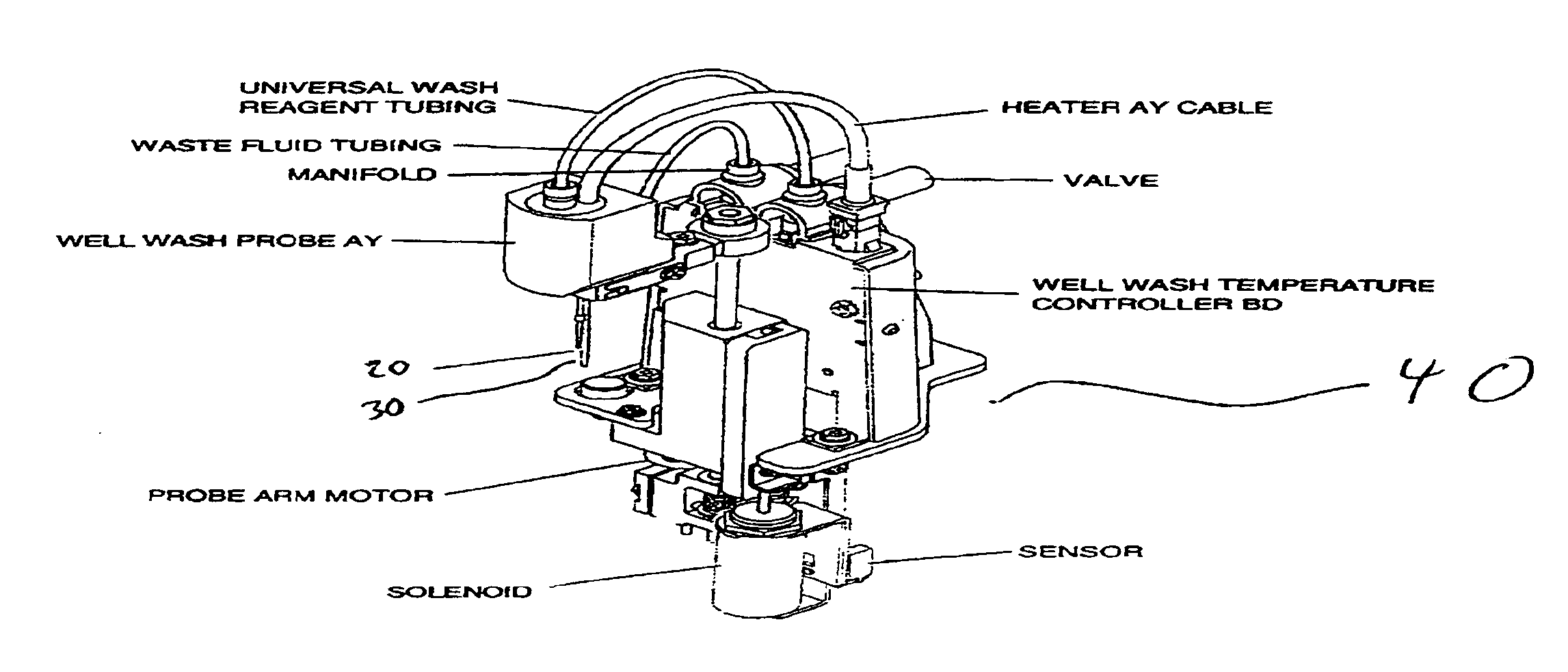
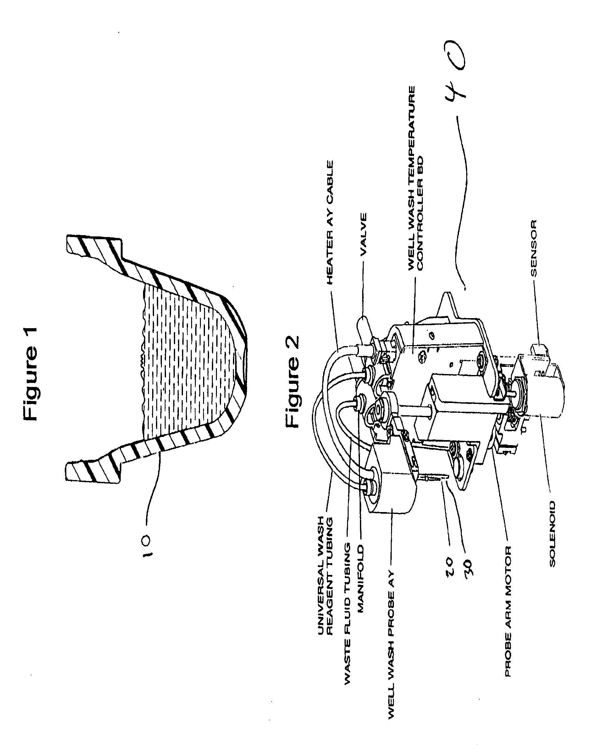
[0052]In a particularly preferred embodiment, the processes described above are employed in an immunodiagnostic assay analyzer, such as those described in U.S. Pat. No. 6,069,561 and copending U.S. application Ser. No. 09 / 482,599 filed Jan. 13, 2000 entitled “Failure Detection in Automated Clinical Analyzers,” both of which are incorporated by reference in their entireties. In preferred immunodiagnostic analyzers, the container is cup-shaped. Preferred containers are 0.35 ml, conical containers coated with a material complementary to the reagents. Container coatings can comprise materials such as streptavidin and / or other materials useful for immunochemical analysis as is well known in the art to facilitate binding by a biotinylated antigen or antibody to which an analyte binds as part of the assay chemistry. An exemplary container 10 is shown in FIG. 1. Also preferred are separate wash dispense and aspirating probes, such as the wash dispense 20 and aspiration nozzles 30 in wash unit 40 shown in FIG. 2.
[0053]In a typical immunodiagnostic analyzer, the analyzer is categorized into systems and subsystems of components that perform different processes in the sequence of measuring a sample for an analyte, such as those described in the '599 application. A typical process involves a sample being dispensed into a container that may or may not already have a reagent present in the container that is dispensed by a reagent metering system. After the reagent is added, the sample is diluted, if necessary, and then incubated. After incubation, the container is washed, in this instance according to the inventive wash. After washing, a signal reagent is added, followed by further incubation, if necessary, optionally followed by the surface removal embodiment. The signal produced by the combination bound analyte / signal reagent is read by the appropriate detector, e.g., a luminometer.

Problems solved by technology

This means that small amounts of unbound material present during the measurement portion of the process, particularly signal producing material, can produce a substantial adverse impact on performance.
Considerable erroneous signal can be generated when the wash fluid makes contact with unbound material in the upper regions of the container where the material is re-hydrated but not removed.
Another problem with known systems that remove fluid by aspiration is that the outer surface of an aspirating nozzle can become contaminated with the wash fluid containing unbound material.
This can lead to contamination of the container with unbound material in subsequent wash cycles (in that particular test or across subsequent tests).
Still another problem with known systems that unbound material can reside or float on top of the fluid, even after several wash steps.
This can also interfere with any subsequent analysis of the desired bound material.
Upon the addition of an additional fluid, such as a signal reagent, the unbound material, can float to the surface of the fluid, where it will interfere with subsequent analysis.
This may particularly be the case if the unbound material is horseradish peroxidase (“HRP”), which when bound to denatured protein may also prefer to float on the surface of the signal reagent fluid, where it will combine with the signal associated with bound HRP and create a false signal which will be read, thereby leading to erroneous results.
The problems described above may lead to the unbound material remaining in the test container and possibly interfering with the subsequent analysis of the analyte, leading to tests that need to be repeated at considerable inconvenience and expense due to inaccurate results.
This is not practical for a random access analyzer system since the test element needs to be transported during the soak cycle so other tests elements can be processed.
Even analyzers that fill the test element to the very top of the container may still have issues with not completely removing unbound label at the very top, if there are features in this region that can trap or retain unbound material.
In this process, the last processing step can cause any residual unbound material to flow into a region of the test element where it can interact with the signal generating reagents, thus producing erroneous results.

Method used


Image

  • Wash process for removing undesired components in samples being analyzed
  • Wash process for removing undesired components in samples being analyzed
  • Wash process for removing undesired components in samples being analyzed

Examples


example 1

[0060]Biotin reagent was added to streptavidin-coated containers containing samples to initiate a reaction between biotinylated anti-cTnI antibody, the streptavidin coated container and the cTnI present in the sample. HRP conjugate reagent was also added to initiate a reaction between HRP-conjugated anti-cTnI antibody and the cTnI in the sample. The sample and reagent were then incubated for 8 minutes and 37° C. After incubation, the containers containing the samples were washed according to the present invention and according to the known wash process. Following washing, signal reagent containing a luminol derivative, a peracid salt and a substituted acetanilide electron transfer agent was added to produce luminescence that was read using a luminometer. The results are shown in the graph set forth in FIG. 5. As the graph shows, the results using the wash process of the present invention are much more consistent and have fewer outliers than the results using the known wash process.

example 2

[0061]Eight washes were performed with signal reagent aspiration as described above, and eight washes without signal reagent aspiration. The results are shown in the graph set forth in FIG. 6. As the graph shows, the results using the oscillating wash process and signal reagent aspiration of the present invention are much more consistent and have fewer outliers than the results using the known wash process.

example 3

[0062]One set of washes was performed with signal reagent aspirate and oscillating wash. Another set of washes was performed with no signal aspirate or oscillating wash. The results are shown in the graph set forth in FIG. 7. As the graph shows, the results using the wash process of the present invention are much more consistent and have fewer outliers than the results using the known wash process.


PUM

PropertyMeasurementUnit
timeaaaaaaaaaa
incubation timeaaaaaaaaaa
soak timeaaaaaaaaaa

Abstract

A method for removing undesired component(s) from bound desired component(s) in an analysis including: (a) providing a container having a desired component bound thereto and an undesired component; (b) dispensing wash fluid in the container at a first level sufficient to contact a portion of the bound desired component; (c) oscillating wash fluid level in the container; and (d) removing a portion of the wash fluid from the container. A method for removing undesired components from bound desired components in an analysis including steps (a) and (b) above; (c) removing the wash fluid; (d) dispensing a wash fluid at a subsequent level lower than the first level and sufficient to wash the bound desired substrate; and (e) removing wash fluid. Preferably, the desired component is an analyte being measured. Another aspect of the invention provides a method for removing an undesired component from a bound desired component in an analysis by removing a surface portion of fluid containing a portion of the undesired component.

Description

DESCRIPTION OF RELATED APPLICATIONS[0001]This application is a continuation-in-part of U.S. application Ser. No. 10 / 294,876, filed Nov. 14, 2002 now abandoned, the contents of which are incorporated herein by reference in its entirety.BACKGROUND OF THE INVENTION[0002]1. Field of the Invention[0003]The present invention relates to a process for removing an undesired component from a bound desired component, in particular for improving the bound-free separation efficiency. In particular, the present invention relates to a process for separating or washing a bound analyte being analyzed in an automated clinical analyzer from unbound label, particularly without decreasing processing efficiency or speed.[0004]2. Description of the Related Art[0005]Methods and systems for washing containers that hold samples being analyzed, such as analyzers for conducting clinical assays are known, e.g., wash stations in clinical analyzer immunochemical assay systems. For example, U.S. Pat. No. 6,096,561...

Claims


Application Information

Patent Timeline
Patent Type & Authority Patents(United States)
IPC IPC(8): G01N33/00G01N1/40G01N35/00
CPCG01N1/40G01N2035/00564Y10T436/25Y10T436/2575Y10T436/255Y10T436/25625Y10T436/25375Y10T436/25125
Inventor JACOBS, MERRIT N.SKROBACH, ANN M.FOOTE, ANDREW S.MACHULSKIS, ANTHONY C.
Owner ORTHO-CLINICAL DIAGNOSTICS
Why Eureka
Try Eureka