Head suspension including integral piezoelectric element electrode support member

a piezoelectric element and electrode support technology, applied in the direction of maintaining the head carrier alignment, recording information storage, instruments, etc., can solve the problems of difficult to ensure assembling accuracy, complicated manufacturing processes, and complicated structure, and achieve the effect of improving the assembling accuracy of the head suspension and simplifying the manufacturing process

Active Publication Date: 2012-12-11
NHK SPRING CO LTD
View PDF8 Cites 45 Cited by
  • Summary
  • Abstract
  • Description
  • Claims
  • Application Information

AI Technical Summary

Benefits of technology

[0011]An object of the present invention is to provide a head suspension consisting of a reduced number of parts to support a piezoelectric element and capable of simplifying manufacturing processes and improving assembling accuracy.
[0013]This aspect of the present invention reduces the number of parts to support the piezoelectric element, thereby simplifying the manufacturing processes and improving assembling accuracy of the head suspension.

Problems solved by technology

These related arts involve many parts to complicate the structure for supporting the piezoelectric element.
As a result, the head suspensions according to the related arts complicate manufacturing processes and make it difficult to secure assembling accuracy.

Method used


Image

  • Head suspension including integral piezoelectric element electrode support member
  • Head suspension including integral piezoelectric element electrode support member
  • Head suspension including integral piezoelectric element electrode support member

Examples


embodiment 1

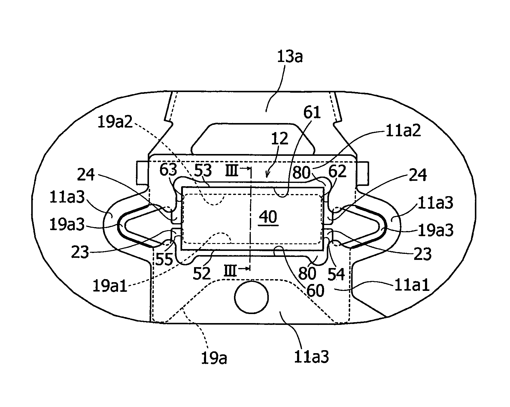
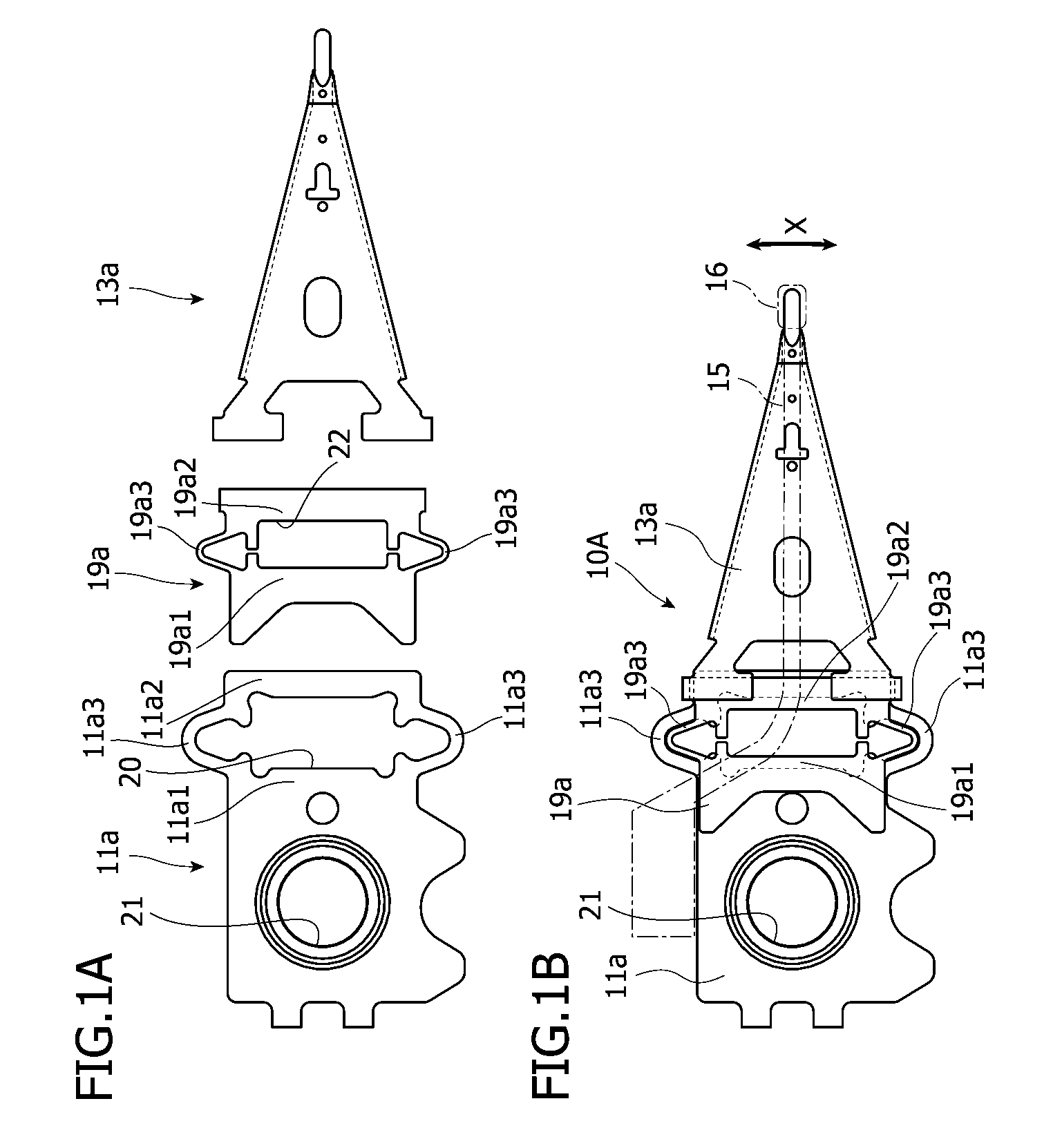
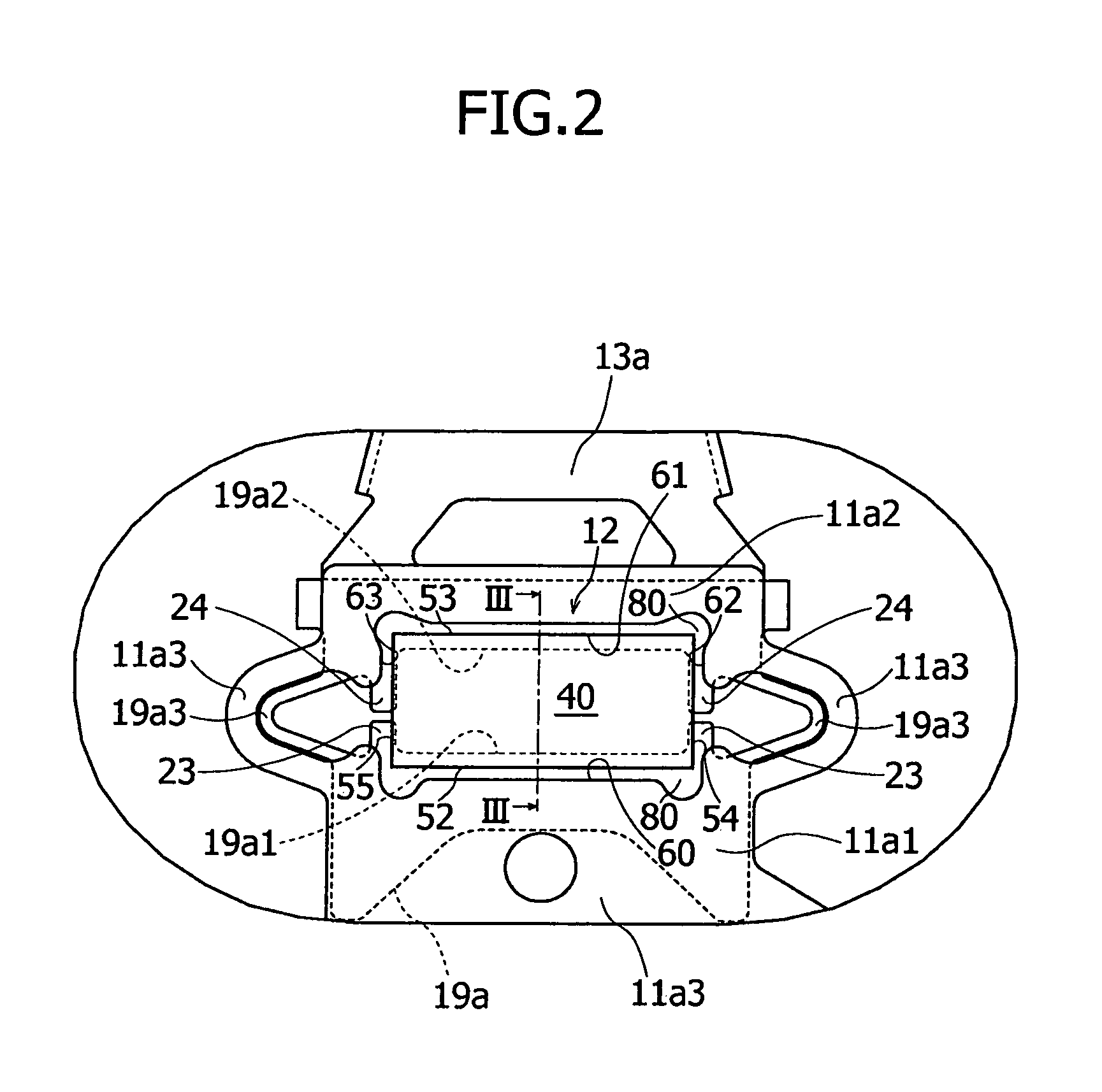
[0025]First, a head suspension will be explained with reference to FIGS. 1A to 3 in which FIG. 1A illustrates essential parts of the head suspension, FIG. 1B illustrates the head suspension, FIG. 2 is an enlarged top view illustrating a part around a piezoelectric element of the head suspension, and FIG. 3 is a sectional view taken along a line of FIG. 2.

[0026]In the following explanation, a base plate side of the head suspension is referred to as a base end or a rear end and a load beam side thereof is referred to as a front end or a front side. A surface side of the head suspension is a side opposite to a side where a magnetic disk is arranged and a back or bottom side of the head suspension is the side where a magnetic disk is arranged.

[0027]The head suspension 10A according to Embodiment 1 has a base plate 11a, a load beam 13a, a support member 19a, and a piezoelectric actuator 12.

[0028]The piezoelectric actuator 12 consists of a piezoelectric ceramic element (hereinafter refer...

embodiment 2

[0070]A head suspension will be explained in detail with reference to FIGS. 4A, 4B, and 5 in which FIG. 4A illustrates essential parts of the head suspension, FIG. 4B illustrates the head suspension, and FIG. 5 is an enlarged top view illustrating a part around a piezoelectric element of the head suspension.

[0071]The head suspension 10B of Embodiment 2 is basically the same as the head suspension 10A of Embodiment 1 except the configuration of a support member, and therefore, the parts common to the two embodiments are represented with the same reference marks to omit overlapped explanations.

[0072]In Embodiment 1, a part related to, for example, the base plate 11a is represented with “11a” plus a numeral. Like this, in Embodiment 2, a part related to, for example, a base plate 11b is represented with “11b” plus a numeral. This style of expression is to easily distinguish the different embodiments from each other.

[0073]Parts having similar reference marks such as the base end part “...

embodiment 3

[0083]A head suspension will be explained in detail with reference to FIGS. 6A, 6B, and 7 in which FIG. 6A illustrates essential parts of the head suspension, FIG. 6B illustrates the head suspension, and FIG. 7 is an enlarged top view illustrating a part around a piezoelectric element of the head suspension.

[0084]The head suspension 10C of Embodiment 3 is basically the same as the head suspension 10B of Embodiment 2 except the configuration of a support member, and therefore, the parts common to the two embodiments are represented with the same reference marks to omit overlapped explanations. Mainly explained hereunder is a difference between Embodiments 2 and 3.

[0085]According to Embodiment 2, the base end support 13b1 and front end support 13b2 of the support member 25 are connected to each other with the support links 13b3 outside the piezoelectric element 40.

[0086]According to Embodiment 3, a support member 27 of the head suspension 10C has a base end support 13c1, a front end ...


PUM

PropertyMeasurementUnit
thicknessaaaaaaaaaa
thicknessaaaaaaaaaa
thicknessaaaaaaaaaa

Abstract

A head suspension has a base plate, a load beam, and a piezoelectric element that is centrally located and deforms in response to applied power to precisely move a front end of the load beam. The head suspension includes an opening formed in the base plate to receive the piezoelectric element and a support member joined with the base plate, partly protruding into the opening, and configured to support an electrode of the piezoelectric element. The support member includes a pair of integral supports to support the electrode, and a pair of integral support links to connect the supports to each other outside the piezoelectric element.

Description

BACKGROUND OF THE INVENTION[0001]1. Field of the Invention[0002]The present invention relates to a head suspension for a disk drive incorporated in an information processing apparatus such as a personal computer.[0003]2. Description of Related Art[0004]Small-sized, precision information devices are rapidly advancing, and for use with such devices, needs for micro-actuators capable of conducting positioning control for very small distances are increasing. Such micro-actuators are highly needed by, for example, optical systems for correcting focuses and inclination angles, ink jet printers for controlling ink heads, and magnetic disk drives for controlling magnetic heads.[0005]To meet the needs, the applicant of the present invention has proposed in Japanese Unexamined Patent Application Publication No. 2002-50140 a head suspension for a disk drive, including a base plate, a connection plate having a hinge thinner than the base plate, a load beam provided with a flexure, and a piezoel...

Claims


Application Information

Patent Timeline
Patent Type & Authority Patents(United States)
IPC IPC(8): G11B21/10G11B5/596
CPCG11B5/4833G11B5/4873
Inventor HANYA, MASAOANDO, TOSHIKI
Owner NHK SPRING CO LTD
Why Eureka
Try Eureka