
Method of designing and manufacturing cam device and three-dimensional design-support computer program for the same

a cam device and computer program technology, applied in the direction of electric programme control, configuration cad, instruments, etc., can solve the problems of not having a suitable design support program, requiring long time and many steps, and the power of the cam device often does not match the customer's request, so as to achieve easy design, reduce the number of design steps, and achieve the effect of avoiding shortening the performan

Inactive Publication Date: 2012-12-11
SANKYO OILLESS IND
View PDF12 Cites 3 Cited by
  • Summary
  • Abstract
  • Description
  • Claims
  • Application Information

AI Technical Summary

Benefits of technology

This solution enables customers to easily design cam devices that meet specific requirements within limited spaces, reducing the need for repeated exchanges and significantly improving design efficiency, while ensuring the cam device manufacturer maintains control over design know-how, thereby shortening the production lead time.

Problems solved by technology

However, in the case of the cam devices as the standard products as described above, various factors such as size, an amount of motion, a processing power, a returning power, and a moment power of the cam device often do not match the customers' requests due to the restrictions of the cam device mounting spaces in the press dies.
However, for example, in the case of three-dimensional design-support software on the basis of a computer program used in design of cam device (CAD: Computer Aided Design or Computer Assisted Drafting, Computer Assisted Drawing), there is no suitable design-support program which contributes to easy designing of the desired cam devices and is capable of designing the cam without leaking the manufacture's design know-how in the relationship between the customers and the manufacturers as matters now stand.
Therefore, repeated exchanges between the customers and the manufactures are necessary to confirm and correct the designed dimensions including details of the cam devices, thereby requiring long time and many steps.
However, the cam device manufacturers side has concern about the leak of the design know-how, so that the software that the manufactures use cannot be handed to the customer as-is.

Method used


Image

  • Method of designing and manufacturing cam device and three-dimensional design-support computer program for the same
  • Method of designing and manufacturing cam device and three-dimensional design-support computer program for the same
  • Method of designing and manufacturing cam device and three-dimensional design-support computer program for the same

Examples


Embodiment Construction

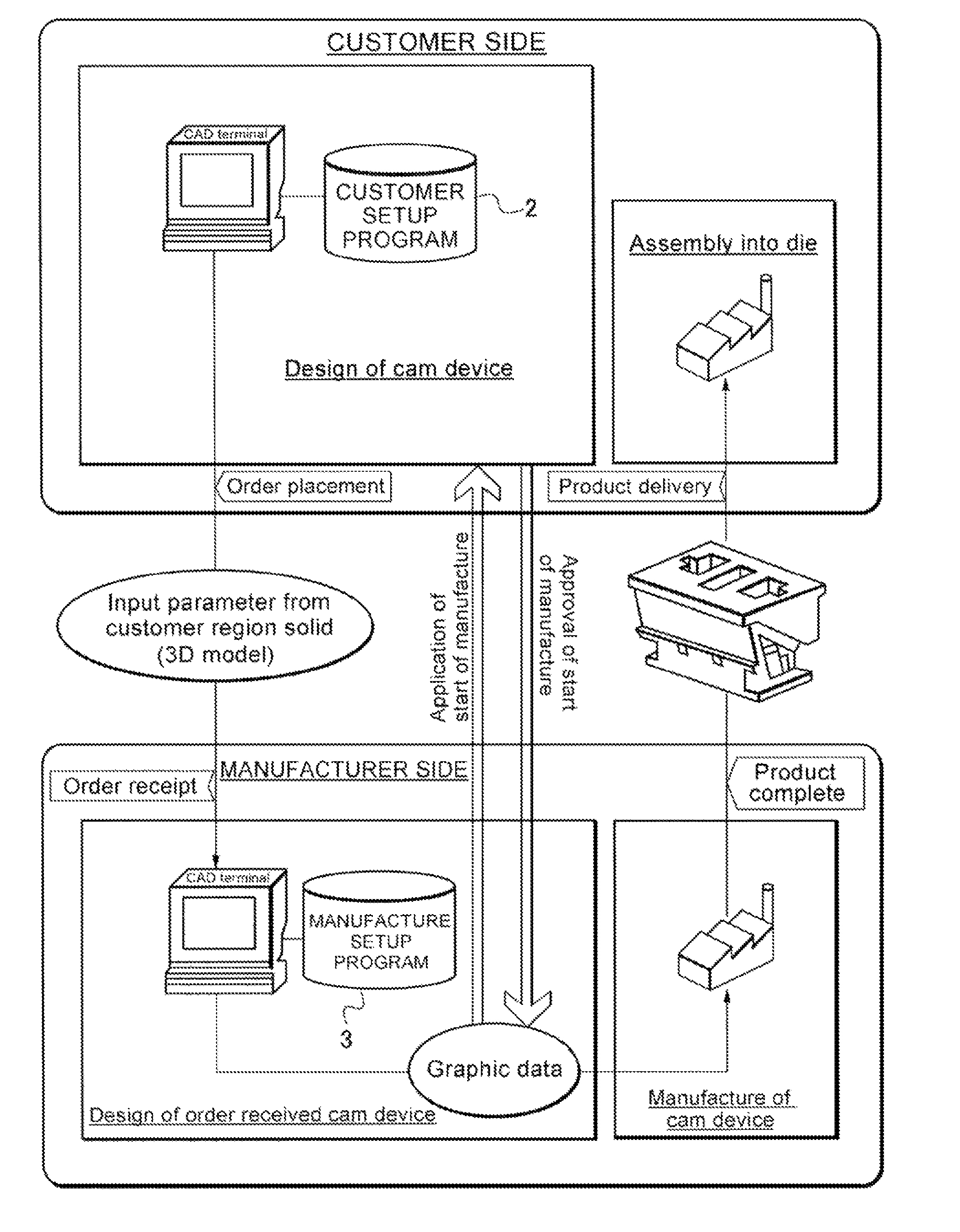
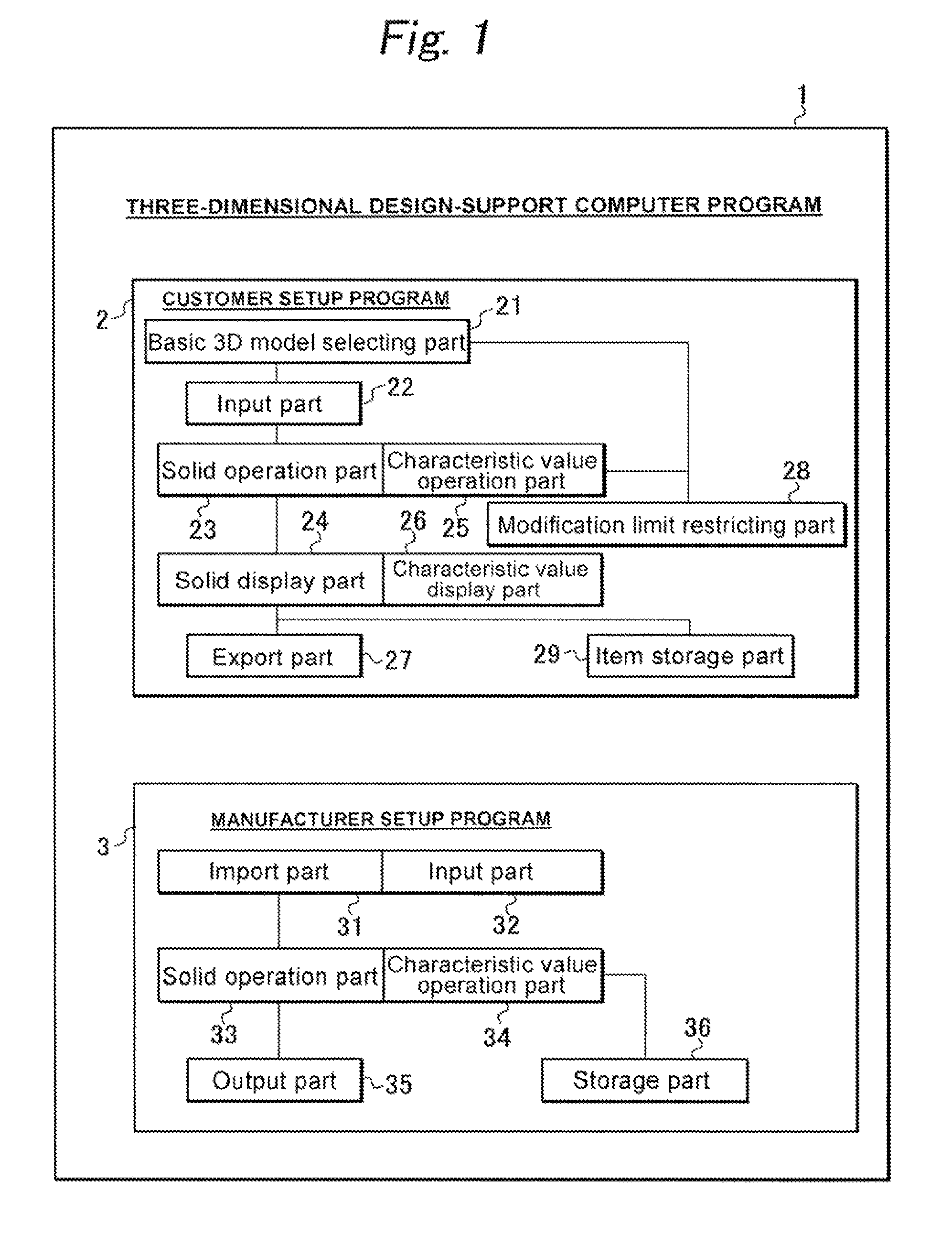
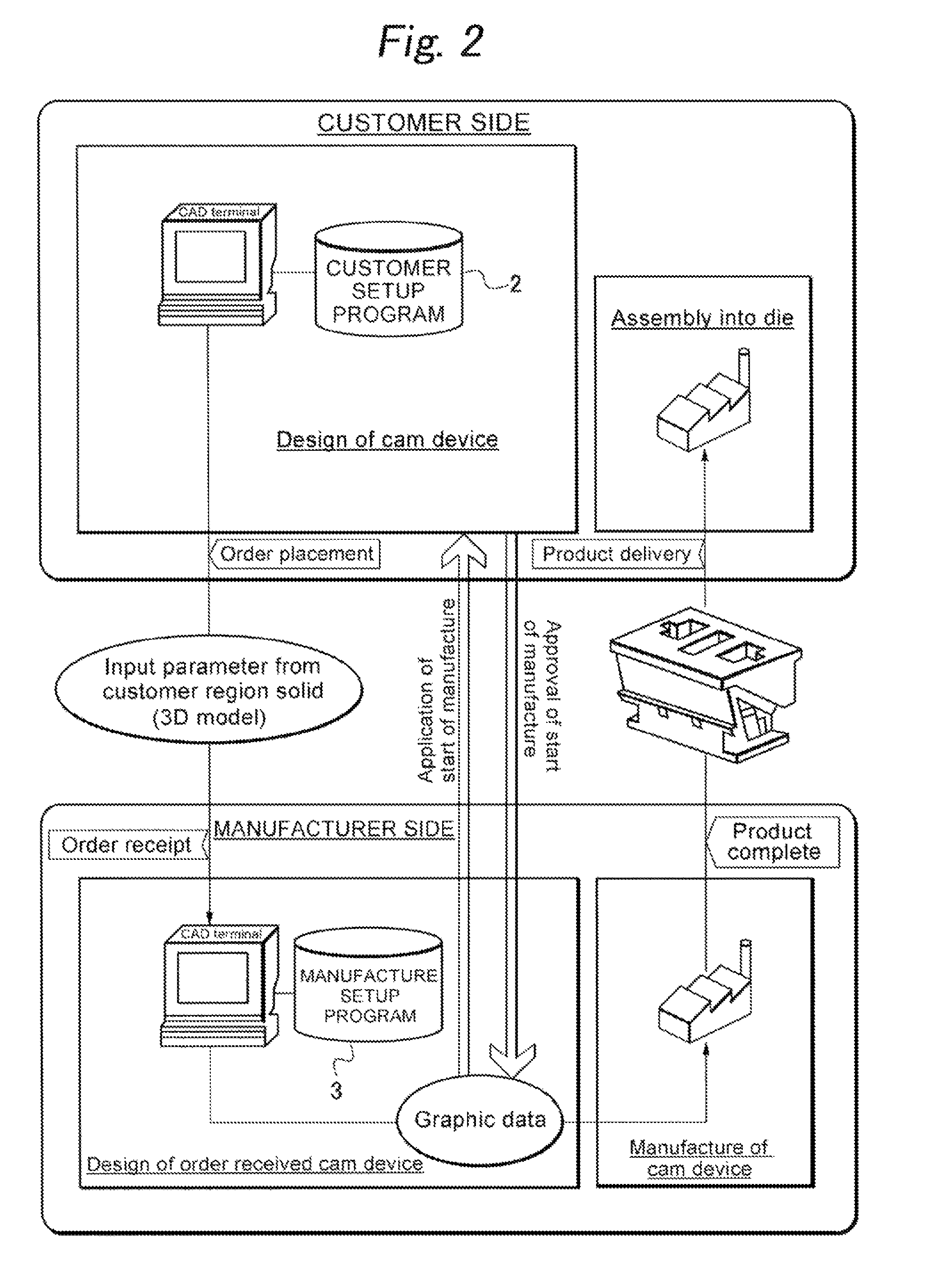
[0021]FIG. 1 shows a three-dimensional design-support computer program used for implementing a method of designing and manufacturing a cam device according to an embodiment of the invention, which includes a customer setup program 2 for customers and a manufacturer setup program 3 for cam device manufactures.

[0022]The customer setup program 2 includes a basic 3D model selecting part 21 which causes a display device (monitor) to display a plurality of basic 3D models prepared according to the size and the usage of the cam device and causes a customer to select one of models. The customer setup program 2 also includes an input part 22 having parameter items for entering basic setup points relating to the shape of a cam device on the basis of a basic 3D model selected by the basic 3D model selecting part 21. The customer setup program 2 includes at least a solid operation part 23 configured to modify a region solid of the cam device to be displayed on the display device according to th...


PUM


Abstract

There is provided a method of designing and manufacturing a cam device using a three-dimensional design-support computer program including a customer setup program for customers and a manufacture setup program for cam device manufactures being configured to generate different finenesses in 3D models and characteristic values of cam performance as a result of design of the cam device, and being configured to obtain a result which indicates the same cam device except for fineness and the required calculation items when the same parameters are loaded. The customer setup program is lent from the cam device manufacture to the customer, and detailed design to constructional details of the cam device is performed using the manufacture setup program on the basis of design data created using the customer setup program and handed to the cam device manufacturer, whereby the cam device is manufactured on the basis of a detailed design drawing.

Description

BACKGROUND OF THE INVENTION[0001]1. Field of the Invention[0002]The present invention relates to a method of designing and manufacturing a cam device used by being mounted on a press die for processing works such as automobile panels, the method being configured to determine the shapes of the cam device according to processing abilities or the like required by customers (users such as automobile manufacturers which are in need of the cam device), and also to a three-dimensional design-support computer program that efficiently supports the design of the cam device.[0003]2. Prior Art[0004]In the prior art, a cam device to be used for a press die (or referred to as “cam unit”) is selected from those presented on catalogues or the like as standard products on the basis of requirements of customers in many cases. However, in the case of the cam devices as the standard products as described above, various factors such as size, an amount of motion, a processing power, a returning power, an...

Claims


Application Information

Patent Timeline
Patent Type & Authority Patents(United States)
IPC IPC(8): G06F19/00G06Q30/00G05B19/418G06F17/50G06Q30/06G06Q50/00G06Q50/04
CPCG06F17/50G06F2217/02G06F2111/20G06F30/00
Inventor KAKO, HIROYOSHINAKAMURA, SATOSHIISHIZAKA, AKIHITO
Owner SANKYO OILLESS IND
Learn More