
Correcting in-line spectrophotometer measurements in the presence of a banding defect

a banding defect and in-line spectrophotometer technology, applied in the direction of instruments, nmr measurements, image enhancement, etc., can solve the problems of significant contributors of artifacts, variation is one of the most visible and undesirable artifacts, and systems such as the dc8002/7002 are susceptible to a banding d

Active Publication Date: 2012-12-11
XEROX CORP
View PDF7 Cites 6 Cited by
  • Summary
  • Abstract
  • Description
  • Claims
  • Application Information

AI Technical Summary

Benefits of technology

The patent describes a new system and method for correcting color measurements made by an in-line spectrophotometer color correction system. This system can detect and remove a banding defect that can occur when printing constant value color patches. The method involves analyzing the data collected by the system and adjusting the distance between repeats of the color patch to synchronize the measurements with the banding wavelength. This allows for more accurate and reliable color measurements, even in the presence of a banding defect.

Problems solved by technology

The scanline spacing variation is a significant contributor of artifacts in the marking process.
For example, halftone banding caused by scanline spacing variation is one of the most visible and undesirable artifacts, appearing as light and dark streaks across a printed page perpendicular to the process direction.
Such one dimensional image density variation in the process direction are often periodic and can result from errors in the mechanical motion of rotating components within a marking engine.
Systems such as the DC8002 / 7002 are susceptible to a banding defect.
Current ILS implementations do not include mechanisms to robustly deal with banding.
The accuracy of the profiles and channel-by-channel correction are limited by the accuracy of the patch measurements.

Method used


Image

  • Correcting in-line spectrophotometer measurements in the presence of a banding defect
  • Correcting in-line spectrophotometer measurements in the presence of a banding defect
  • Correcting in-line spectrophotometer measurements in the presence of a banding defect

Examples


Embodiment Construction

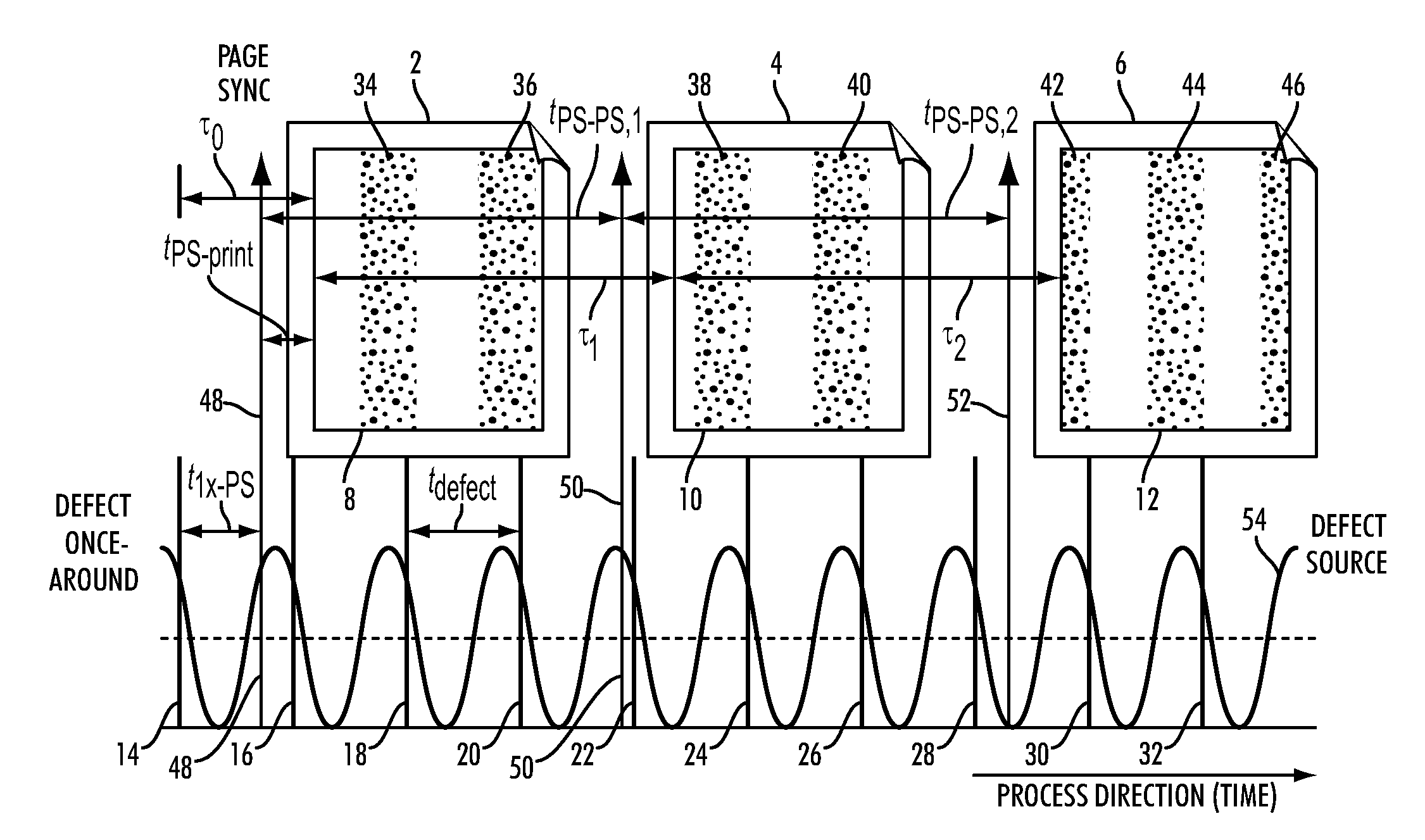
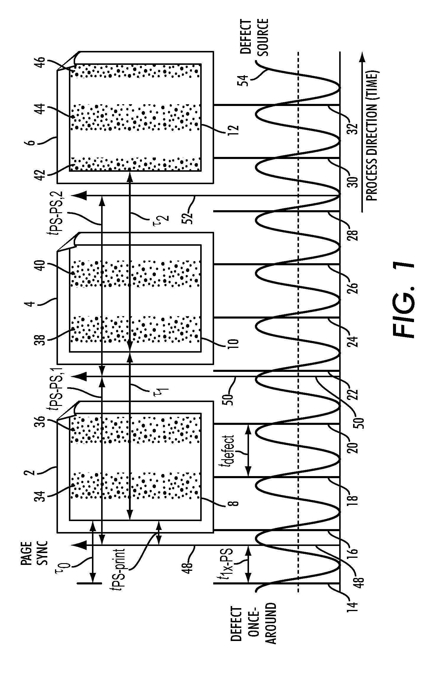
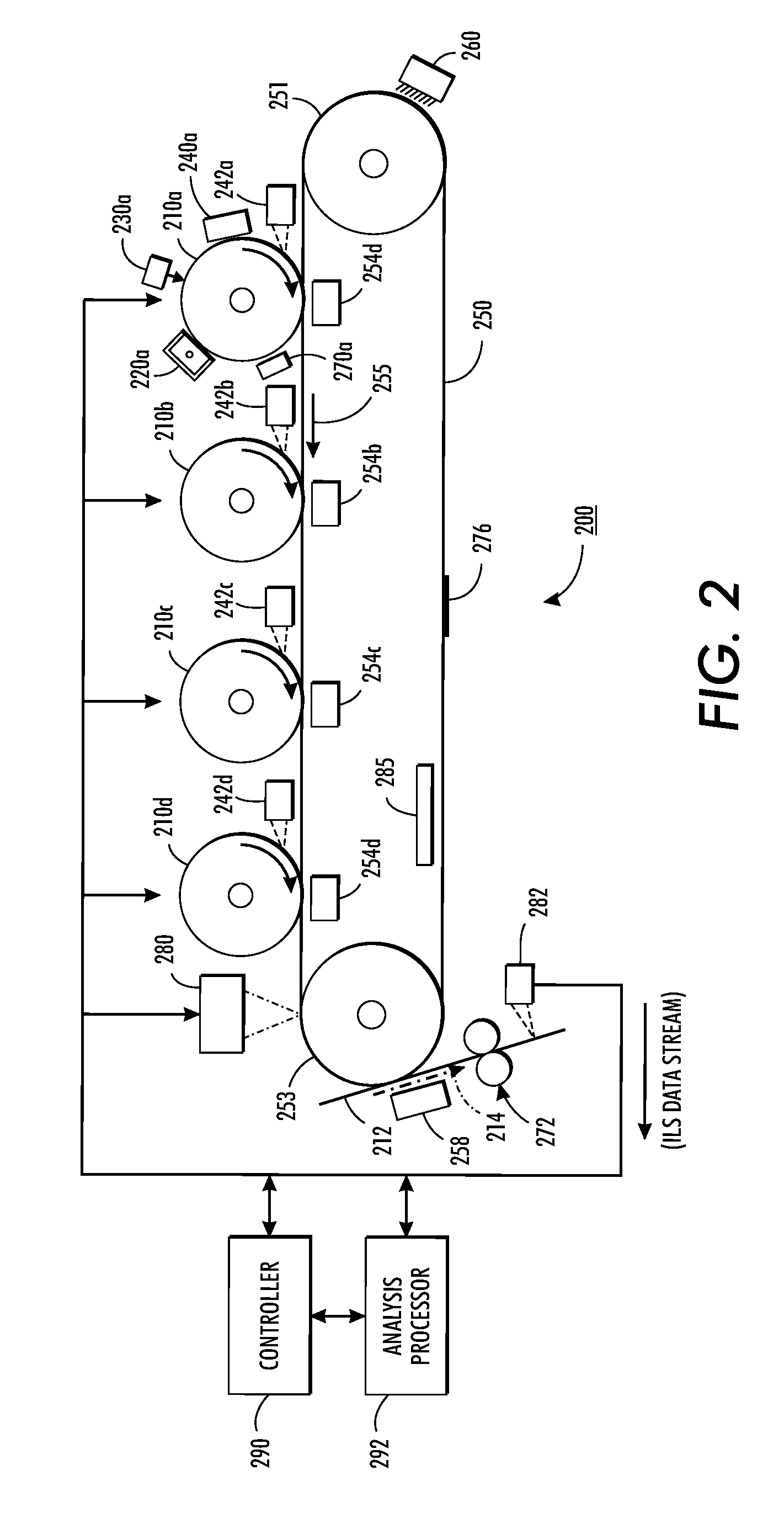
[0018]What is disclosed is novel system and method for detecting and correcting for In-Line-Spectrophotometer (ILS) measurements of constant value patches in the presence of banding in multi-function document reproduction systems.

[0019]It should be understood that one of ordinary skill in this art should be readily familiar with printer quality monitoring and troubleshooting techniques, particularly those which relate to detecting and quantifying xerographic noise, and analyses of scanned test patterns to determine frequency spectra of structured noise components. Those of ordinary skill would be familiar with the text: “Digital Color Imaging Handbook”, 1st Ed., CRC Press (2003), ISBN-13: 97808-4930-9007, and “Control of Color Imaging Systems: Analysis and Design”, CRC Press (2009), ISBN-13: 97808-4933-7468, both of which are incorporated herein in their entirety by reference.

[0020]A “reflectance sensing device”, as used herein, refers to a spectrophotometric device having a plurali...


PUM


Abstract

What is disclosed is a novel system and method for detecting and correcting for In-Line-Spectrophotometer (ILS) measurements of constant value patches in the presence of banding in multi-function document reproduction systems. The present system analyzes the ILS data stream to identify structured noise components due to banding. An FFT is performed on each L*a*b* component in the ILS stream for a single test page. The peak frequencies from the FFT of the L* a* and b* channels are compared. Common frequencies in all 3 channels indicate a banding component. Once the banding frequencies and the banding wavelength are known, the color patch target can be adjusted to ensure the color patches are synchronized to the banding wavelength. By running a series of synchronized patches and averaging results, structured noise can be eliminated. In such a manner, a reduction of banding effects on color calibration can be effectuated.

Description

TECHNICAL FIELD[0001]The present invention is directed to systems and methods for correcting measurements obtained using an in-line spectrophotometer from color test patches in the presence of a banding defect in a digital document reproduction device.BACKGROUND[0002]In a typical multi-function document reproduction system, a photoconductive drum or photoreceptor belt rotates at an angular velocity and, as the photoconductive drum rotates, the drum is electrostatically charged. A latent image is exposed line-by-line onto the photoconductive drum using a scanning laser and, for instance, a rotating polygon mirror. The latent image is developed by electrostatically adhering toner particles to the photoconductive drum. The developed image is transferred from the photoconductive drum to the output media such as paper. The toner image on the paper is fused to the paper to make the image on the paper permanent. The surface of the photoconductive drum is cleaned to remove any residual tone...

Claims


Application Information

Patent Timeline
Patent Type & Authority Patents(United States)
IPC IPC(8): G01R33/56G01R33/565
CPCG03G15/5062
Inventor CUSTODE, BEATRIZ CRISTINASCHWEID, STUART ALANBAXTER, III, JAMES EDWARD
Owner XEROX CORP
Learn More