
Method and apparatus for incorporating a low pressure fluid into a high pressure fluid, and increasing the efficiency of the rankine cycle in a power plant

a technology of high-pressure fluid and low-pressure fluid, which is applied in the direction of positive-displacement liquid engines, machines/engines, transportation and packaging, etc., can solve the problems of limited efficiency of mixing of helium and working fluid, and achieve the effect of reducing the power needed and minimizing the stress tension

Inactive Publication Date: 2012-12-18
KAKOVITCH THOMAS
View PDF8 Cites 0 Cited by
  • Summary
  • Abstract
  • Description
  • Claims
  • Application Information

AI Technical Summary

Benefits of technology

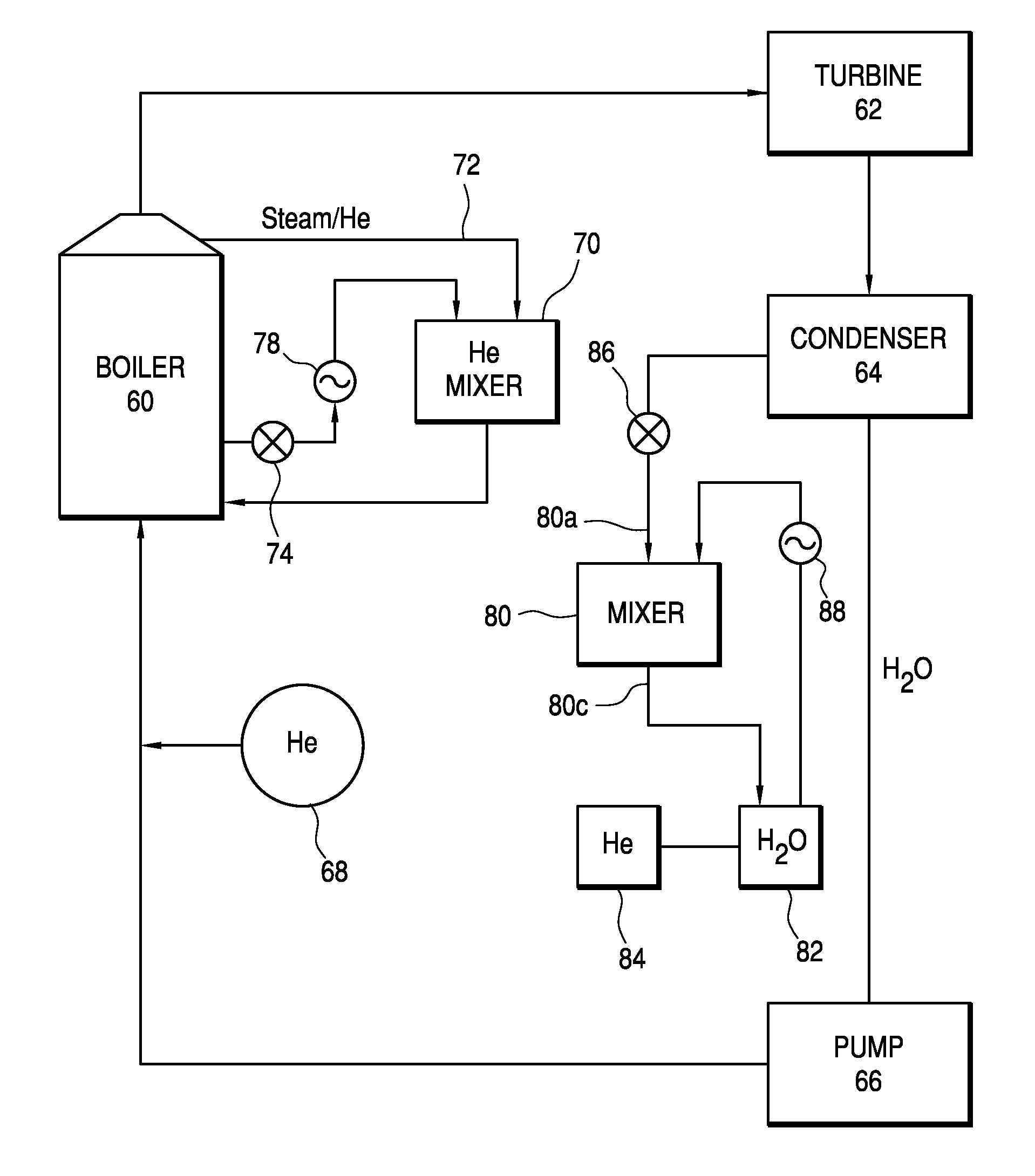
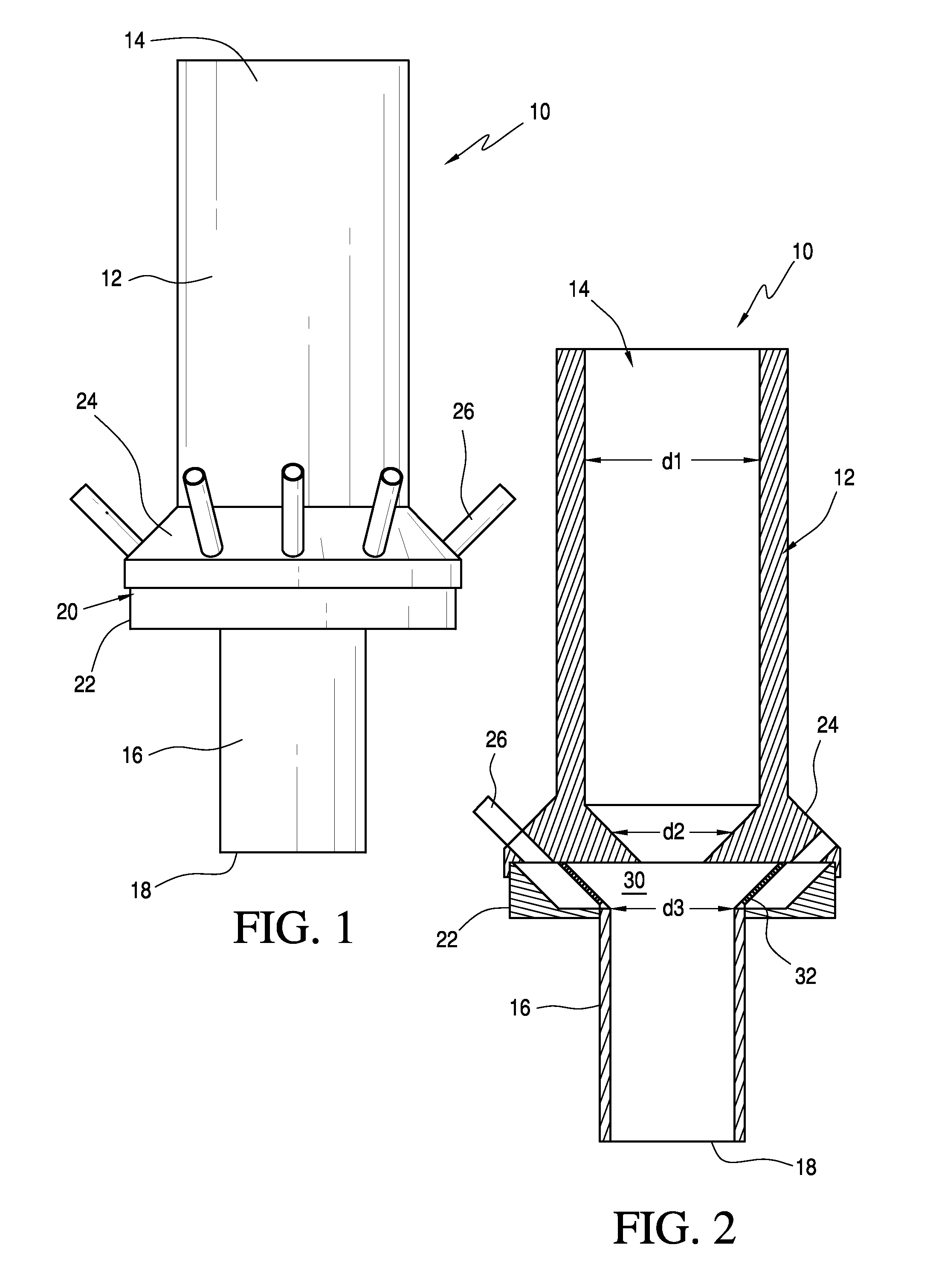
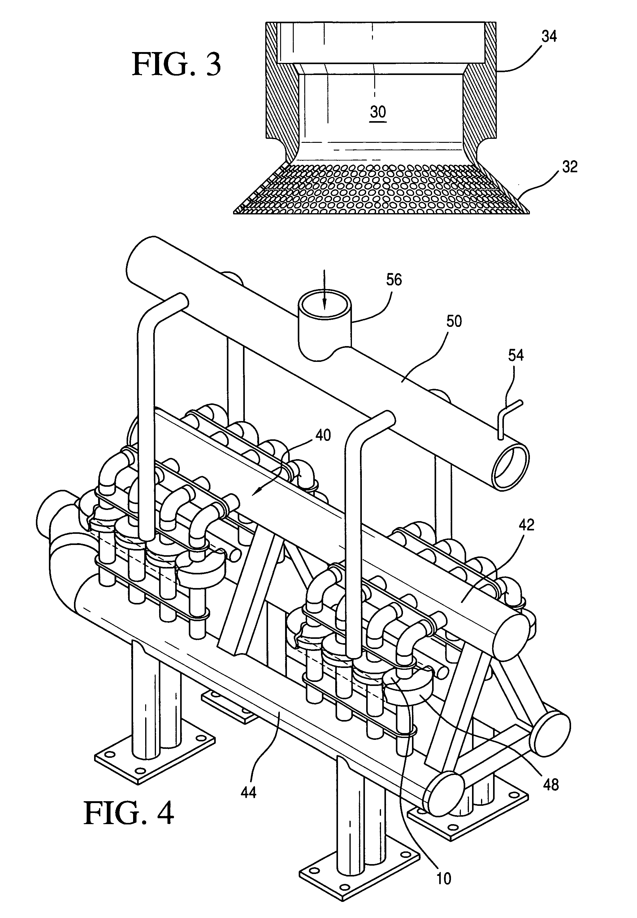
"The invention is a mixing device that can mix fluids with different pressures. It includes a cylindrical section and a conical section with small passages and holes. The device can increase the efficiency of power generation by mixing a light fluid into a high-pressure working fluid. A skid can be used to connect multiple mixing devices in parallel. The mixing device has minimal stress tension and is designed to withstand high pressure. The invention also includes a helium cycle that can be retrofitted into an existing power plant. The mixing device helps to evacuate helium from the boiler and recompress it back into the boiler, reducing the power necessary to heat the water."

Problems solved by technology

Because the helium is returned to the boiler, however, the efficiency of the mixing of the helium with the working fluid is limited.
Greater efficiency would be expected by mixing the helium with the compressed working fluid before heating in the boiler, but this presents problems, since the compressed working fluid is at a very high pressure, possibly in the range of 2000-4000 psig, while the helium is at a very low pressure, which makes mixing difficult.

Method used


Image

  • Method and apparatus for incorporating a low pressure fluid into a high pressure fluid, and increasing the efficiency of the rankine cycle in a power plant
  • Method and apparatus for incorporating a low pressure fluid into a high pressure fluid, and increasing the efficiency of the rankine cycle in a power plant
  • Method and apparatus for incorporating a low pressure fluid into a high pressure fluid, and increasing the efficiency of the rankine cycle in a power plant

Examples


example

[0043]The mixing device of the invention (FIG. 4) is used to recycle steam from the steam drum of a boiler to the water drum, in a circuit as shown in FIGS. 5 and 6, with turbine and compressor. The following measurements were made:

[0044]P1=1000 psi

[0045]P2=923 psi

[0046]P2j=78.026 psi increase over P2

[0047]P1j=14.7 psi

[0048]T1j(ambient temperature)=520° R (460+60° F.)

[0049]water flow=200 gpm

[0050]Pout=14.7 psi

[0051]T2j=840.269° (temperature of compressed air)

[0052]The work done on the turbine due to air compression was calculated at 8.9839 hp.


PUM

PropertyMeasurementUnit
angleaaaaaaaaaa
pressureaaaaaaaaaa
angleaaaaaaaaaa

Abstract

A mixing device for incorporating a light gas at low pressure into a working fluid at a very high pressure includes a mixing section in the form of a truncated conical section between the an inlet and an outlet, a plurality of inlets for the light gas into the mixing section, and a plurality of passages through the truncated conical section into a cylindrical section leading to the outlet.

Description

[0001]This application claims the benefit of U.S. Provisional Application 61 / 083,527 filed Jul. 25, 2008.BACKGROUND OF THE INVENTION[0002]The invention relates to the field of mixing fluids, where one fluid is at a very low pressure and one fluid is at a very high pressure, and to use such fluid mixing to increase the megawatt output of a steam power plant, with a reduction of fuel consumption, by incorporating a newly modified mechanical system that is able to evacuate gas from very low pressures, and to recompress the gas to very high pressures.[0003]In my U.S. Pat. Nos. 5,255,519 and 5,444,981 (incorporated herein by reference), I proposed increasing the efficiency in the generation of power, particularly electric power, using the Rankine cycle, by incorporating a light gas in the working fluid to increase the compressibility of the working fluid, and hence the expansion of the fluid in the cycle. In the closed system disclosed in those patents, a light, condensable gas, typicall...

Claims


Application Information

Patent Timeline
Patent Type & Authority Patents(United States)
IPC IPC(8): F01K25/06F04B23/08B01F23/10
CPCB01F3/02B01F5/0413B01F5/043F01K21/04B01F23/10B01F25/312B01F25/31243
Inventor KAKOVITCH, THOMAS
Owner KAKOVITCH THOMAS
Learn More