
Process for manufacturing a low-attenuation optical fiber

a manufacturing process and low-attenuation technology, applied in the direction of glass making apparatus, instruments, material analysis, etc., can solve the problems of attenuation of optical fibers, premature closure of holes, and gradual reduction of power of optical signals propagating along optical fibers

Active Publication Date: 2012-12-18
PRYSMIAN SPA
View PDF11 Cites 0 Cited by
  • Summary
  • Abstract
  • Description
  • Claims
  • Application Information

AI Technical Summary

Benefits of technology

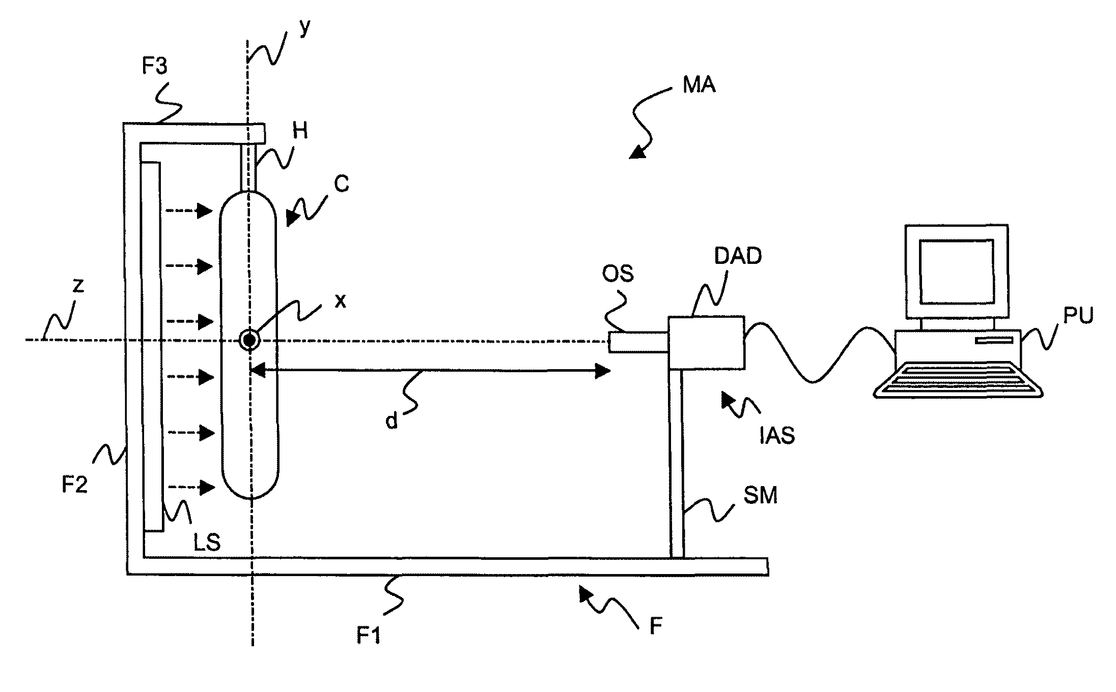
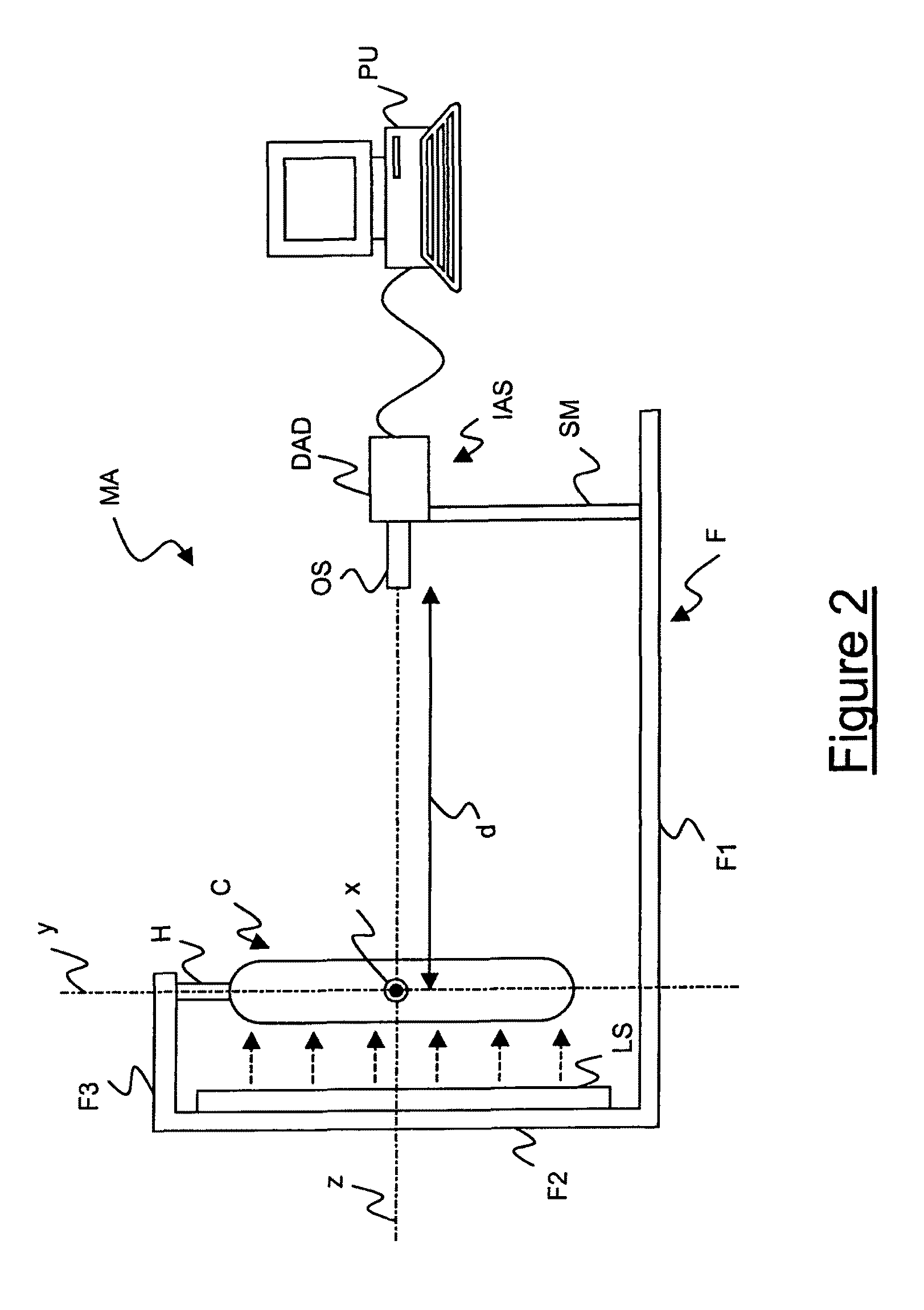
The present invention relates to a process for manufacturing optical fibers, which involves measuring the geometric characteristics of the glass core preform axial hole to check the quality of the preform. By measuring the axial hole, defective preforms can be discarded, or re-processed, at an early stage of the manufacturing process, thereby avoiding to discard the optical fibers at the end of the process. The measuring step can be carried out before or after the drying and consolidating steps, and the image of the whole glass core preform can be obtained by acquiring at least two images at different angles and processing them. The invention aims to improve the quality and efficiency of the optical fiber manufacturing process.

Problems solved by technology

In particular, due to attenuation, an optical signal propagating along an optical fiber gradually reduces its power.
Attenuation in optical fibers is mainly due to impurities or defects into the core.
Indeed, a diameter larger that 0.4 mm could result in a non negligible OH contamination after the extraction of the preform from the furnace, while a diameter lower than 0.05 mm could induce a premature closure of the hole, in particular during the successive stretching step, so that bubbles and voids are inevitably formed inside the core.

Method used


Image

  • Process for manufacturing a low-attenuation optical fiber
  • Process for manufacturing a low-attenuation optical fiber
  • Process for manufacturing a low-attenuation optical fiber

Examples


Embodiment Construction

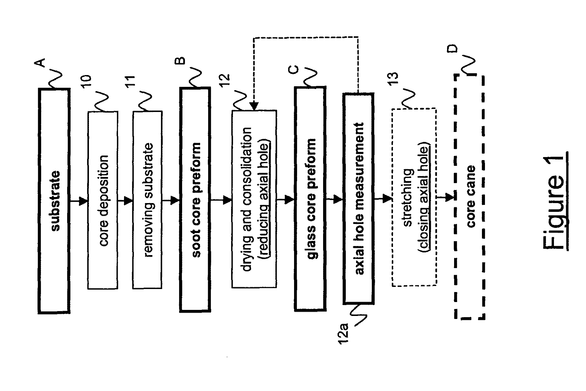
[0064]FIG. 1 schematically shows a flow chart including the steps for providing a core cane in a process for manufacturing an optical fiber, specifically a low-attenuation optical fiber. Said process comprises a core deposition step (step 10) wherein a core layer is laid down on a cylindrical substrate A. During the core deposition step a plurality of chemical substances, typically comprising oxides of silica and germanium, is deposited on the substrate A by using an OVD apparatus. The substrate is typically a rod. The rod is preferably made from glass or Alumina. The substances deposited onto the substrate form the core and the inner cladding portion. During the core deposition step, the reactant flow may be varied (in particular, germanium concentration is typically decreased in time) so as to obtain a predetermined refractive index profile. In particular, by controlling the reactant flow it is possible to obtain a desired ratio between core radius and external radius of the core ...


PUM

PropertyMeasurementUnit
aspect ratioaaaaaaaaaa
wavelengthsaaaaaaaaaa

Abstract

A process for manufacturing an optical fiber, includes the steps of: a) producing a soot core preform by depositing a core material on a substrate; b) removing the substrate from the soot preform leaving an axial cavity along the longitudinal axis of the soot core preform; (c) drying and consolidating the soot core preform so as to obtain a glass core preform having an axial hole corresponding to the axial cavity; d) reducing a diameter of the axial hole; and e) stretching the glass core preform so as to substantially close the axial hole, wherein the process further includes the step of measuring at least one geometric characteristic of the axial hole of the glass core preform.

Description

CROSS REFERENCE TO RELATED APPLICATION[0001]This application is a national phase application based on PCT / EP2006 / 067505, filed Oct. 17, 2006, the content of which is incorporated herein by reference.TECHNICAL FIELD[0002]The present invention relates to an optical fiber manufacturing process.[0003]In particular, the present invention relates to a process for manufacturing an optical fiber which comprises the step of measuring at least one geometric characteristic of a glass core preform.[0004]More in particular, the present invention relates to a process for manufacturing an optical fiber which comprises the step of measuring at least one geometric characteristic of an axial hole of a glass core preform.[0005]Furthermore, the present invention relates to a method for measuring at least one geometric characteristic of an axial hole of a glass core preform, specifically in a process for manufacturing an optical fiber.BACKGROUND ART[0006]Telecommunication optical systems use optical fib...

Claims


Application Information

Patent Timeline
Patent Type & Authority Patents(United States)
IPC IPC(8): C03B37/07
CPCC03B37/01466
Inventor RUZZIER, MARCORUOCCHIO, CRISTIANOCOCCHINI, FRANCOADIGRAT, ANTONIO
Owner PRYSMIAN SPA
Learn More