Component mounting device

a technology of mounting device and component, which is applied in the direction of rod connection, image analysis, image enhancement, etc., can solve the problems of inability to obtain reflected light suitable for checking conceivably difficult to accurately check the quality of the inserted state of the filter inside the nozzle shaft, and ineffective detection of poor inserted state of the filter. , to achieve the effect of significantly reducing or preventing the start of production

Pending Publication Date: 2022-06-16
YAMAHA MOTOR CO LTD
View PDF0 Cites 0 Cited by
  • Summary
  • Abstract
  • Description
  • Claims
  • Application Information

AI Technical Summary

Benefits of technology

[0017]In the aforementioned structure in which the quality of the inserted state of the filter is detected, the controller is preferably configured to perform a control to detect the quality of the inserted state of the filter at a time of production start and at a time of replacement of the filter. Thus, for example, the controller performs a control to detect the quality of the inserted state of the filter at the time of production start such that the start of production can be significantly reduced or prevented when the inserted state of th

Problems solved by technology

However, in the surface mounter described in International Publication No. 2018/179048, it is conceivable that the quality of the inserted states of the filters inside the nozzle shafts may be checked using the light reflected from the surfaces of the filters, and thus depending on the surface conditions (dirt, color, etc.) of the filters, reflected light suitable for checking the quality of the inserted states of the filters inside the nozzle shafts may not be obt

Method used


Image

  • Component mounting device
  • Component mounting device
  • Component mounting device

Examples


modified examples

[0113]The embodiment disclosed this time must be considered as illustrative in all points and not restrictive. The scope of the present disclosure is not shown by the above description of the embodiment but by the scope of claims for patent, and all modifications (modified examples) within the meaning and scope equivalent to the scope of claims for patent are further included.

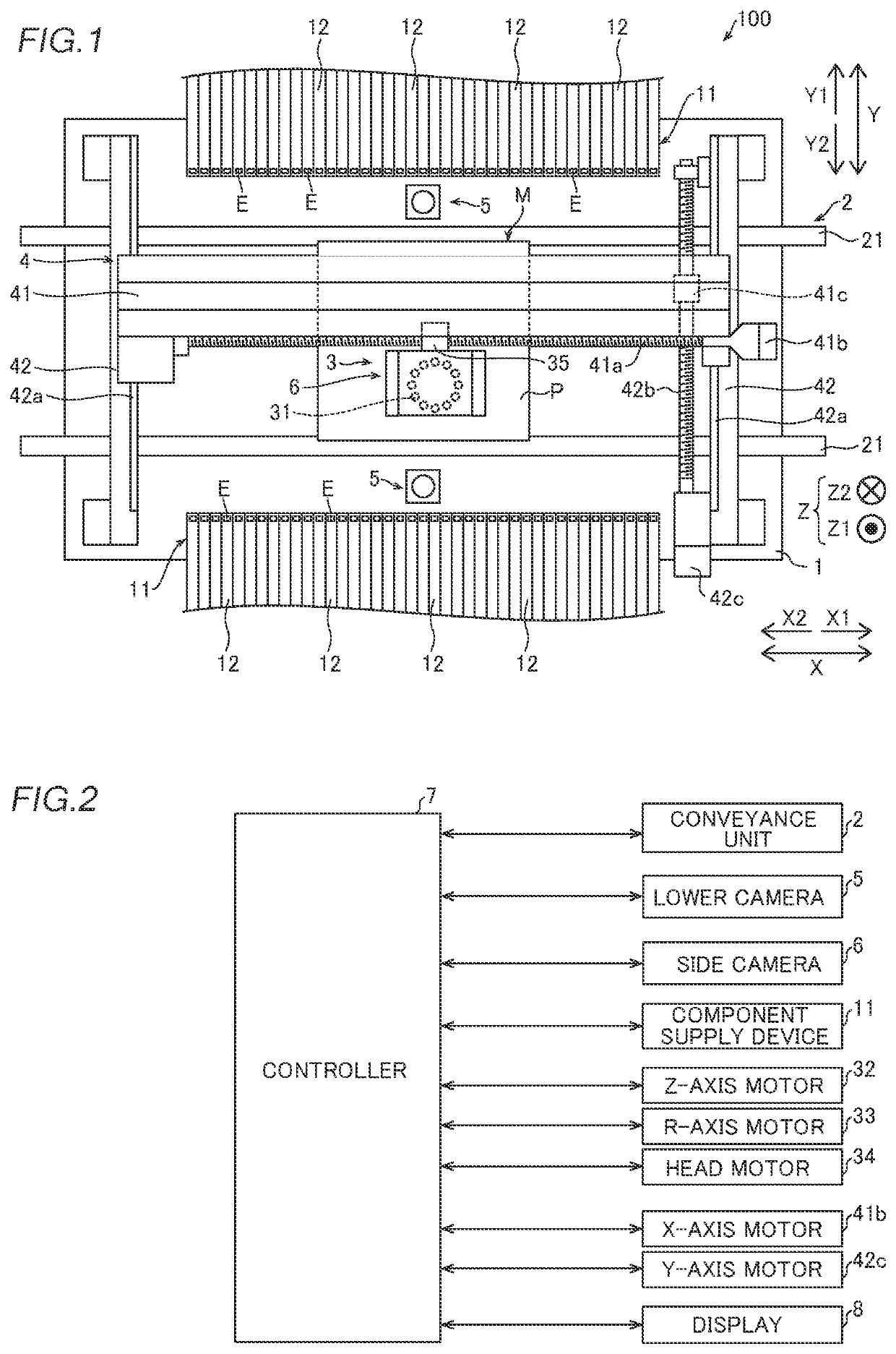
[0114]For example, while the example in which the component mounting device includes the rotary head unit has been shown in the aforementioned embodiment, the present disclosure is not restricted to this. In the present disclosure, the component mounting device may include an in-line head unit in which a plurality of heads are linearly arranged.

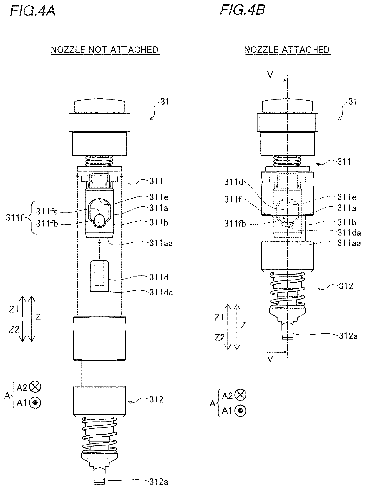
[0115]While the example in which the nozzle shaft includes the fluid passage opening in the side wall on the A1 direction side has been shown in the aforementioned embodiment, the present disclosure is not restricted to this. In the present disclosure, the nozzle shaft d...


PUM


Abstract

A component mounting device includes a nozzle shaft. The nozzle shaft includes a filter and a filter state checking portion. The filter state checking portion is configured to allow light to pass therethrough from a first side to a second side of the nozzle shaft in an axially orthogonal direction according to an inserted state of the filter.

Description

CROSS-REFERENCE TO RELATED APPLICATION[0001]This application is a National Stage of International Patent Application No. PCT / JP2019 / 017157, filed Apr. 23, 2019, the entire content of which is incorporated herein by reference.BACKGROUNDTechnical Field[0002]The present disclosure relates to a component mounting device, and more particularly, it relates to a component mounting device including a filter inserted in a nozzle shaft.Background Art[0003]Conventionally, a component mounting device including a filter inserted in a nozzle shaft is known. Such a component mounting device is disclosed in International Publication No. 2018 / 179048, for example.[0004]International Publication No. 2018 / 179048 discloses a surface mounter (component mounting device) that suctions components and mounts the components on a printed circuit board. This surface mounter includes nozzle shafts and suction nozzles configured to be attachable to and detachable from the nozzle shafts and suction the components....

Claims


Application Information

Patent Timeline
IPC IPC(8): F16B7/04G06T7/00
CPCF16B7/0406G06T2207/30164G06T7/0004H05K13/04G06T2207/10152
Inventor ITO, KOTA
Owner YAMAHA MOTOR CO LTD
Why Eureka
Try Eureka