Laser processing device and laser processing system

a laser processing and laser processing technology, applied in the direction of measurement devices, using reradiation, instruments, etc., can solve the problems of difficult to accurately measure the distance between the work and the processing head in consideration of the absolute position accuracy of the robot or repeatability, cost increase, and difficulty in simply measuring the distance between the work and the processing head, so as to achieve the effect of checking the quality of the processing

Active Publication Date: 2019-07-11
FANUC LTD
View PDF0 Cites 0 Cited by
  • Summary
  • Abstract
  • Description
  • Claims
  • Application Information

AI Technical Summary

Benefits of technology

[0008]It is therefore an object of the present invention to provide a laser processing device and a laser processing system capable of measuring a distance between a work and a processing head accurately and simply and capable of checking the quality of processing in real time during the processing.
[0016]According to the present invention, by using a light source for processing as a light source for measurement, a distance between a work and a processing head can be measured and a processing quality can be checked at the same time.

Problems solved by technology

However, the method of patent document 1 finds it difficult to measure a distance between a work and a processing head accurately in consideration of absolute position accuracy of the robot or repeatability.
This involves a problem of cost increase and a problem relating to space in the processing head.
Regarding the method of installing the measuring instrument outside the processing head, simply measuring a distance between the work and the processing head is made difficult by the necessity to provide the measuring instrument separately.
Further, the methods described above have not been devised on condition that the quality of processing be checked in real time during the processing.

Method used


Image

  • Laser processing device and laser processing system
  • Laser processing device and laser processing system
  • Laser processing device and laser processing system

Examples


first embodiment

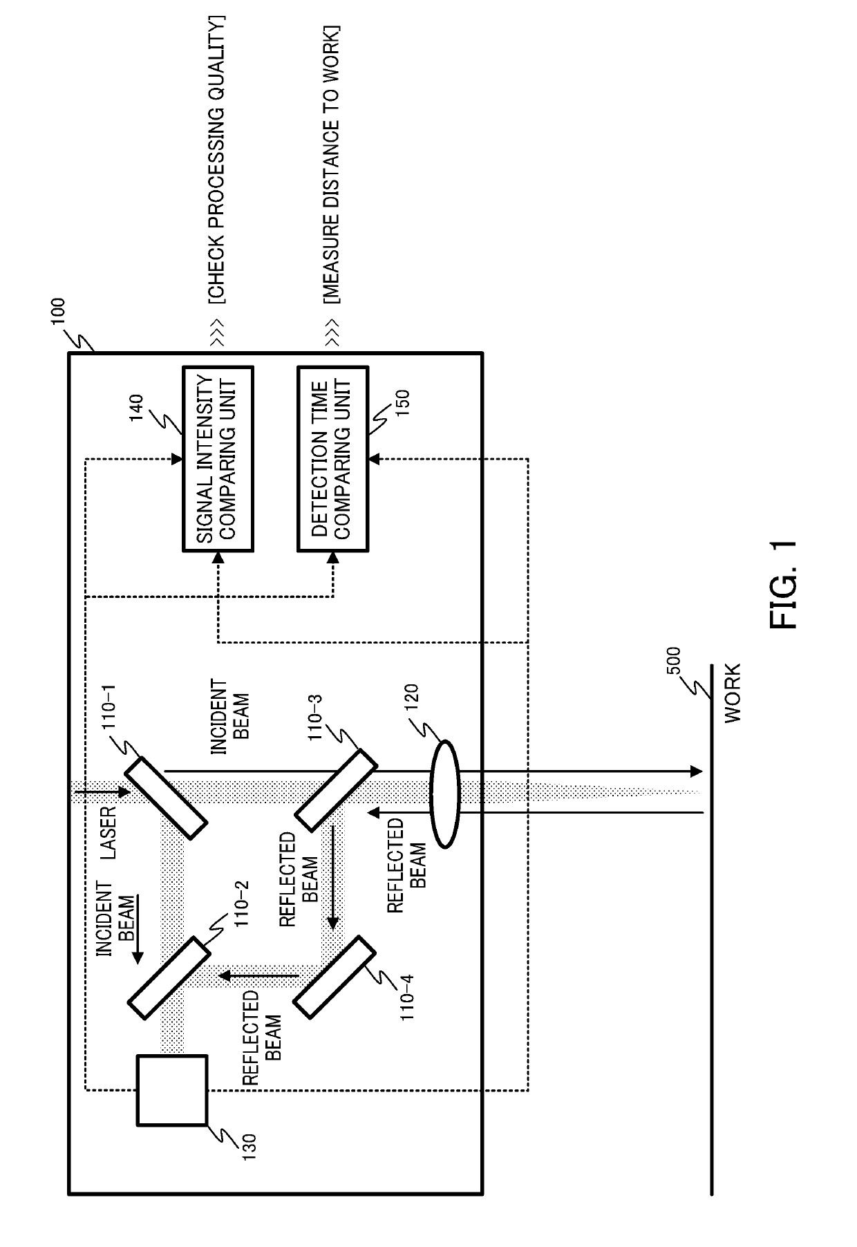
[0021]A first embodiment of the present invention will be described in detail by referring to FIG. 1.

[0022]For laser processing using a laser processing device, grasping the position of the laser processing device and that of a work relative to each other is important for obtaining a favorable processing quality. According to the present invention, to calculate a distance between the laser processing device and the work, a time of flight (TOF) method is employed by using a processing light source. More specifically, this method is to measure time of flight of a processing beam from projection of the processing beam to a subject to receipt of a reflected beam, and to multiply the measured time of flight by the speed of flight of the processing beam. Optical path splitting means such as a beam splitter is installed for measurement of the time of flight. According to the first embodiment, an incident beam on a work and a reflected beam from the work both resulting from splitting by the...

second embodiment

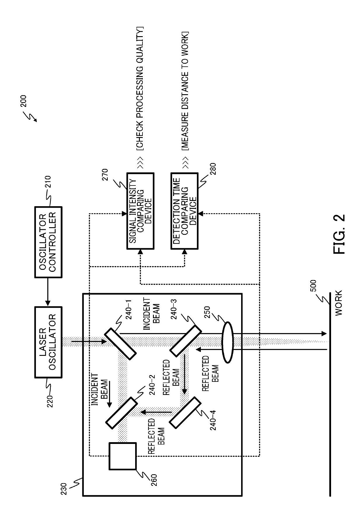
[0031]A second embodiment of the present invention will be described in detail by referring to FIG. 2.

[0032]According to the first embodiment, the laser processing device 100 includes the signal intensity comparing unit 140 and the detection time comparing unit 150 as its constituting elements. By contrast, according to the second embodiment, instead of providing a signal intensity comparing unit and a detection time comparing unit to the laser processing device 100, a signal intensity comparing device 270 and a detection time comparing device 280 separately from the laser processing device 100 are provided.

[0033]More specifically, a laser processing system 200 with a laser processing device 230 according to the second embodiment includes a laser oscillator 220, an oscillator controller 210 that controls the laser oscillator 220, the signal intensity comparing device 270, and the detection time comparing device 280 in addition to the laser processing device 230.

[0034]Like the laser ...

third embodiment

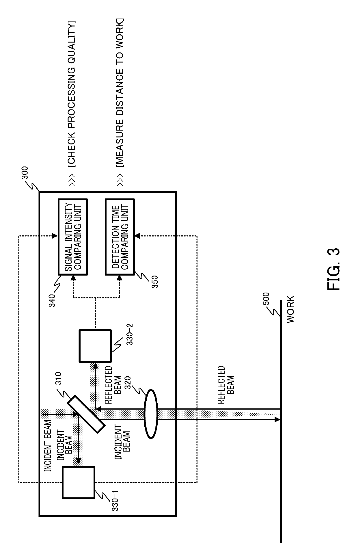
[0038]A third embodiment of the present invention will be described in detail by referring to FIG. 3.

[0039]The laser processing device according to each of the first and second embodiments includes the multiple optical path splitting means. By contrast, a laser processing device according to the third embodiment includes only one optical path splitting means and includes multiple photodetectors.

[0040]FIG. 3 shows an example of the configuration of a laser processing device 300 according to the third embodiment. The laser processing device 300 includes optical path splitting means 310, a focusing lens 320, a photodetector 330-1, a photodetector 330-2, a signal intensity comparing unit 340, and a detection time comparing unit 350.

[0041]Only one optical path splitting means 310 is provided in the laser processing device 300. Both the front surface and the back surface of the optical path splitting means 310, viewed from an incident beam or from a reflected beam, function as reflection ...


PUM


Abstract

An object is to provide a laser processing device and a laser processing system capable of measuring a distance between a work and a processing head accurately and simply and capable of checking the quality of processing in real time during the processing. Provided are: a photodetector that detects the intensity of a processing laser beam split by optical path splitting means, and outputs a detection signal having a signal intensity responsive to the detected intensity together with a time of detection of the intensity; a signal intensity comparing unit that compares the signal intensities of multiple detection signals received from the photodetector; and a detection time comparing unit that compares times of detection of multiple intensities. The signal intensity comparing unit measures a processing quality by comparing the signal intensity of a detection signal received from the photodetector responsive to an incident beam on a work and the signal intensity of a detection signal received from the photodetector responsive to a reflected beam from the work. The detection time comparing unit measures a distance between a laser processing device and the work by comparing times of detection of the intensities.

Description

[0001]This application is a Divisional of U.S. application Ser. No. 15 / 642,558 filed Jul. 6, 2017, and is based on and claims the benefit of priority from Japanese Patent Application No. 2016-138626, filed on 13 Jul. 2016, the content of which is incorporated herein by reference.BACKGROUND OF THE INVENTIONField of the Invention[0002]The present invention relates to a laser processing device and a laser processing system for processing of a work using a processing laser beam.Related Art[0003]For laser processing using a laser processing head, a distance between a work and the processing head has been required to be controlled so as to place a focal position of an optical system on the work. A distance between the processing head and the work has not been maintained constantly, particularly in the application of the processing head to remote laser welding performed with a galvanometer scanner gripped by a robot, for example. Hence, for proper processing, the aforementioned distance ha...

Claims


Application Information

Patent Timeline
Patent Type & Authority Applications(United States)
IPC IPC(8): G01S17/10G01S7/497G01S7/481G01S7/486G01S7/4865
CPCG01S17/10G01S7/497G01S7/4812G01S7/4865
Inventor MURAKAMI, YOSHINORI
Owner FANUC LTD
Why Eureka
Try Eureka