
Process for manufacturing a low-attenuation optical fiber

a manufacturing process and low-attenuation technology, applied in the direction of glass making apparatus, manufacturing tools, instruments, etc., can solve the problems of attenuation of optical fibers, premature closure of holes, and gradual reduction of power of optical signal propagating along optical fibers

Active Publication Date: 2010-09-23
PRYSMIAN SPA
View PDF1 Cites 0 Cited by
  • Summary
  • Abstract
  • Description
  • Claims
  • Application Information

AI Technical Summary

Benefits of technology

[0026]The Applicant has found that the OH contamination of a glass core preform as well as the premature closure of the axial hole thereof can be avoided, or at least remarkably reduced, by carrying out a non-destructive control of the axial hole of the glass core preform.
[0027]In particular, the Applicant has found that, by providing the optical fiber manufacturing process with a step of measuring at least one geometric characteristic of the glass core preform axial hole, it is possible to check the quality of 100% produced glass core preforms so that defected preforms can be discarded, or possibly re-processed, at a very early stage of the manufacturing process, thereby avoiding to discard the optical fibers at the end of the manufacturing process thereof.
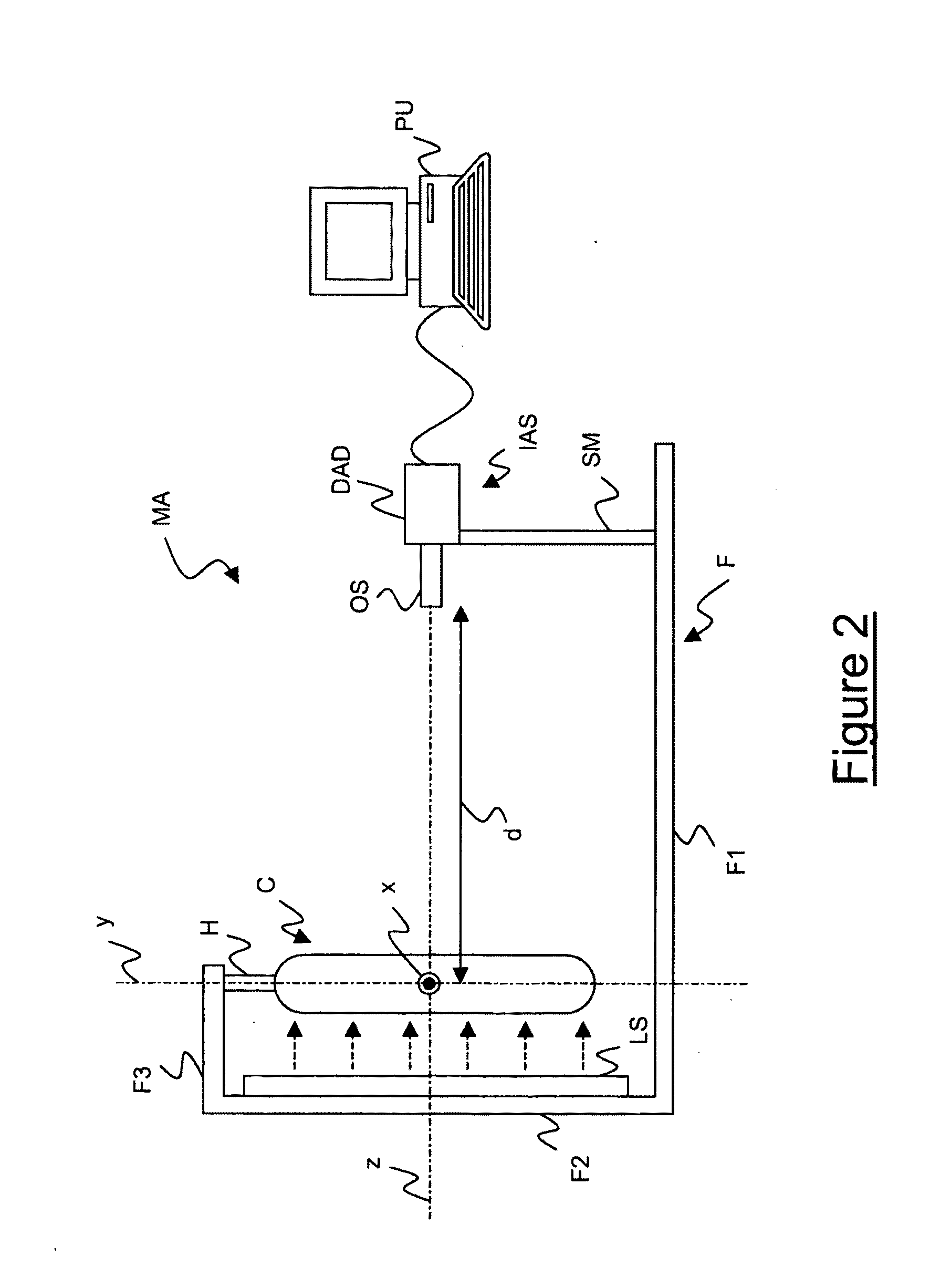
[0044]Preferably, the Applicant has found that two images of the whole glass core preform C, taken by rotating the preform of an angle of 45° to 120°, are generally suitable for obtaining a precise measure in a relatively short time. In the case two images are taken, the preform is preferably rotated of 90°.
[0054]The image processing technique of the present invention comprises an anamorphic optical system designed to produce a vertical magnification which is about 4 times less than the horizontal magnification so that a one-shot image of the whole preform length is obtained, thereby avoiding multiple scanning of the preform length wherein each scanning provides for the image of only a longitudinal portion of the preform length.

Problems solved by technology

In particular, due to attenuation, an optical signal propagating along an optical fiber gradually reduces its power.
Attenuation in optical fibers is mainly due to impurities or defects into the core.
Indeed, a diameter larger that 0.4 mm could result in a non negligible OH contamination after the extraction of the preform from the furnace, while a diameter lower than 0.05 mm could induce a premature closure of the hole, in particular during the successive stretching step, so that bubbles and voids are inevitably formed inside the core.

Method used


Image

  • Process for manufacturing a low-attenuation optical fiber
  • Process for manufacturing a low-attenuation optical fiber
  • Process for manufacturing a low-attenuation optical fiber

Examples


Embodiment Construction

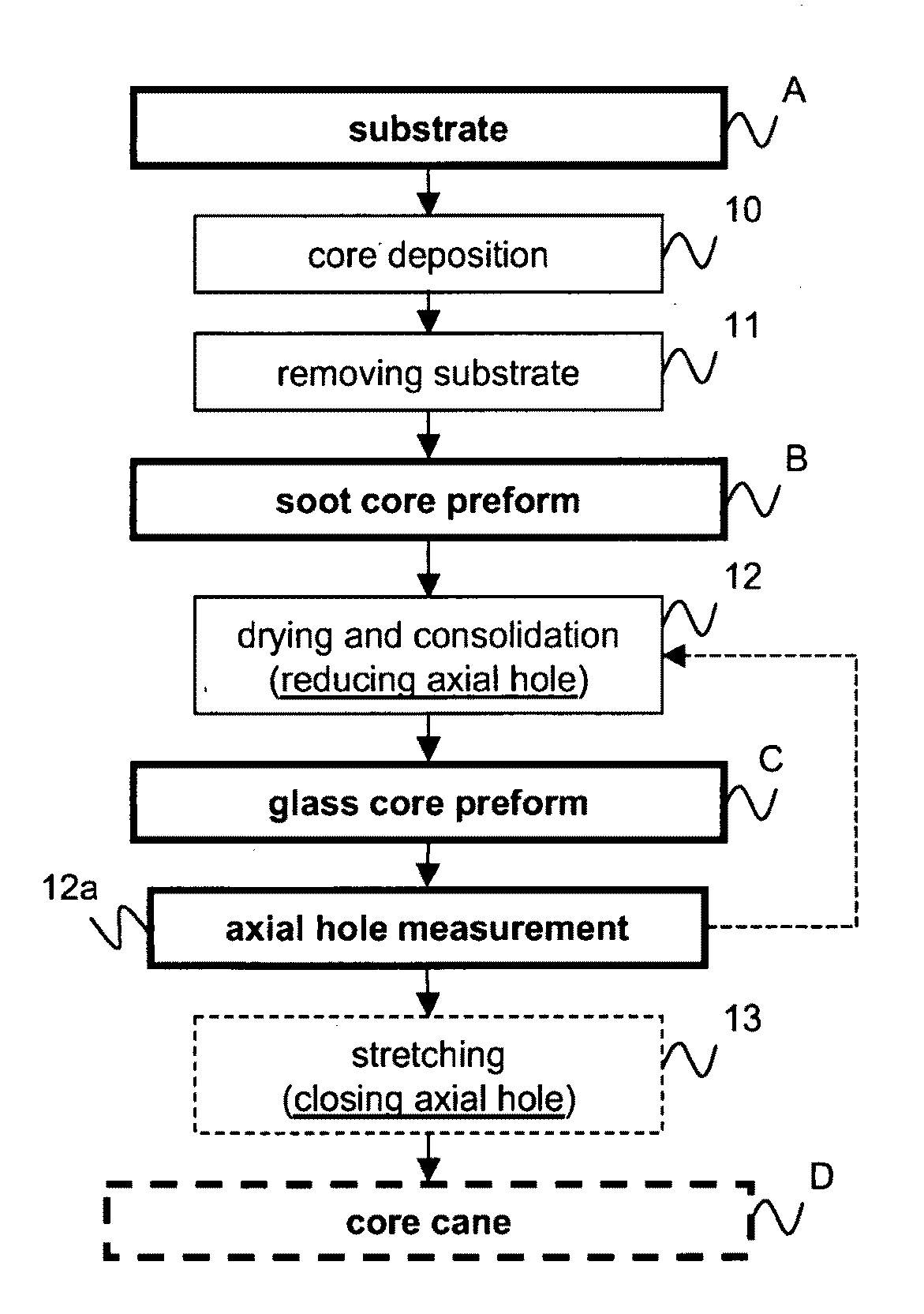
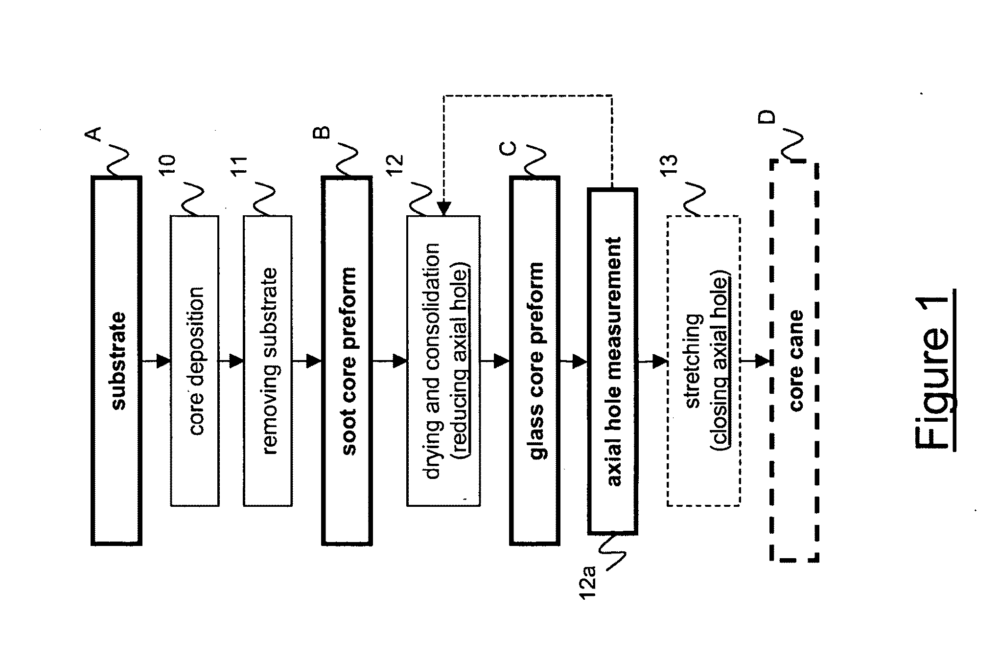
[0063]FIG. 1 schematically shows a flow chart including the steps for providing a core cane in a process for manufacturing an optical fiber, specifically a low-attenuation optical fiber. Said process comprises a core deposition step (step 10) wherein a core layer is laid down on a cylindrical substrate A. During the core deposition step a plurality of chemical substances, typically comprising oxides of silica and germanium, is deposited on the substrate A by using an OVD apparatus. The substrate is typically a rod. The rod is preferably made from glass or Alumina. The substances deposited onto the substrate form the core and the inner cladding portion. During the core deposition step, the reactant flow may be varied (in particular, germanium concentration is typically decreased in time) so as to obtain a predetermined refractive index profile. In particular, by controlling the reactant flow it is possible to obtain a desired ratio between core radius and external radius of the core ...


PUM

PropertyMeasurementUnit
Lengthaaaaaaaaaa
Lengthaaaaaaaaaa
Lengthaaaaaaaaaa

Abstract

A process for manufacturing an optical fiber, includes the steps of: a) producing a soot core preform by depositing a core material on a substrate; b) removing the substrate from the soot preform leaving an axial cavity along the longitudinal axis of the soot core preform; (c) drying and consolidating the soot core preform so as to obtain a glass core preform having an axial hole corresponding to the axial cavity; d) reducing a diameter of the axial hole; and e) stretching the glass core preform so as to substantially close the axial hole, wherein the process further includes the step of measuring at least one geometric characteristic of the axial hole of the glass core preform.

Description

TECHNICAL FIELD[0001]The present invention relates to an optical fiber manufacturing process.[0002]In particular, the present invention relates to a process for manufacturing an optical fiber which comprises the step of measuring at least one geometric characteristic of a glass core preform.[0003]More in particular, the present invention relates to a process for manufacturing an optical fiber which comprises the step of measuring at least one geometric characteristic of an axial hole of a glass core preform.[0004]Furthermore, the present invention relates to a method for measuring at least one geometric characteristic of an axial hole of a glass core preform, specifically in a process for manufacturing an optical fiber.BACKGROUND ART[0005]Telecommunication optical systems use optical fibers as physical means for transporting information through optical signals. An optical signal, while propagating in an optical fiber, undergoes several changes due to various effects occurring into t...

Claims


Application Information

Patent Timeline
IPC IPC(8): C03B37/07G06K9/62
CPCC03B37/01466
Inventor RUZZIER, MARCORUOCCHIO, CRISTIANOCOCCHINI, FRANCOADIGRAT, ANTONIO
Owner PRYSMIAN SPA
Learn More