Threaded joint with pressurizable seal

a threaded joint and seal technology, applied in the field of threaded joints, can solve the problems of affecting the elastic range of the modulus of elasticity, the deformation of the joint seal, and the increasing demands of hydrocarbon hardware and devices, so as to preserve coupling design and performance, and withstand high axial loads

Active Publication Date: 2012-12-18
TENARIS CONNECTIONS
View PDF138 Cites 24 Cited by
  • Summary
  • Abstract
  • Description
  • Claims
  • Application Information

AI Technical Summary

Benefits of technology

[0015]The principal object of the present invention is to provide a joint having an innovative seal ring ensuring both simple and reliable initial make-up and a high sealing efficiency during operation.
[0016]The above mentioned objects are achieved in accordance with the present invention by means of a threaded tube joint defining an axis comprising a male threaded tube, defined as a pin, and a female threaded tube, defined as a box, the pin being adapted to be made up in the box. A seal ring has an external cylindrical surface, an internal surface comprising one or more annular ribs protruding from the internal surface, a first base with at least a portion of a frustoconical shape, a second base with at least a portion of a frustoconical shape axially opposite to the first base. The first and second bases are slanted towards the axis whereby the external surface is wider than the internal surface. The seal ring is interposed between the pin and the box in tight sealing contact with an internal surface of an annular groove of the box by the external cylindrical surface and in tight sealing contact with an external surface of the pin by the annular ribs. Hydraulic actuating means can pressurize the seal ring against said pin to provide improved scalability of the joint.
[0019]The box of the threaded joint incorporating this seal is made in such a way that the seal ring actuates on a cylindrical surface, advantageously that of the tube body, and thus the pin does not need to be modified. In this manner the joint's performance under tension loads remains intact.
[0020]Both the annular groove, non-return valve and seal ring are completely contained within the box wall thickness, this having the advantage of preserving coupling design and performance as well as protecting the sealing system. Full design via FEA and full scale testing yielded optimized interaction of the seal ring with the annular groove, and the threaded joint of the invention can withstand high axial loads.

Problems solved by technology

Searching for oil or, more generally, hydrocarbons has become more demanding in terms of hardware and devices in recent years because oil and gas fields or reservoirs are located deeper or in places difficult to reach and below the sea.
In some applications threaded joints can be subject to deformation of the joint seals.
Modern joints are generally designed with metal to metal seals made by the contact between two surfaces, usually at one end or at both ends of the threaded portion of the joint, interfering in the elastic range of the modulus of elasticity for an appropriate stress magnitude.
It is therefore a design requirement that the joint seals resist penetration of external or internal fluids, or at least do not allow continuous exchange of fluids that have already penetrated the joint with surrounding fluids, in order to reduce the corrosion rate.
When higher contact pressures are needed for the O-ring, then higher geometric interference is required between the O-ring and joint members.
This might cause seal breakage.
However, the bigger the seal ring, the more exposed is it to damage during make up, especially when it is pre-mounted in the box member and it is forced to overcome the entire pin threaded area.
In this case other drawbacks may arise.
Several geometric connection variables that originate during the manufacturing process, such as ovality, eccentricity, and rugosity, introduce uneven interference over the whole circumference of the sealing surfaces, thus producing uneven contact pressures and reducing the sealing capacity.
In practice, sealing capacity due to geometric interference is limited by the geometry, mainly radial sizes and length, of resilient elements in relation to their ability to be dragged during make up across the threads and any other interfering surface without being damaged.

Method used


Image

  • Threaded joint with pressurizable seal
  • Threaded joint with pressurizable seal
  • Threaded joint with pressurizable seal

Examples


Embodiment Construction

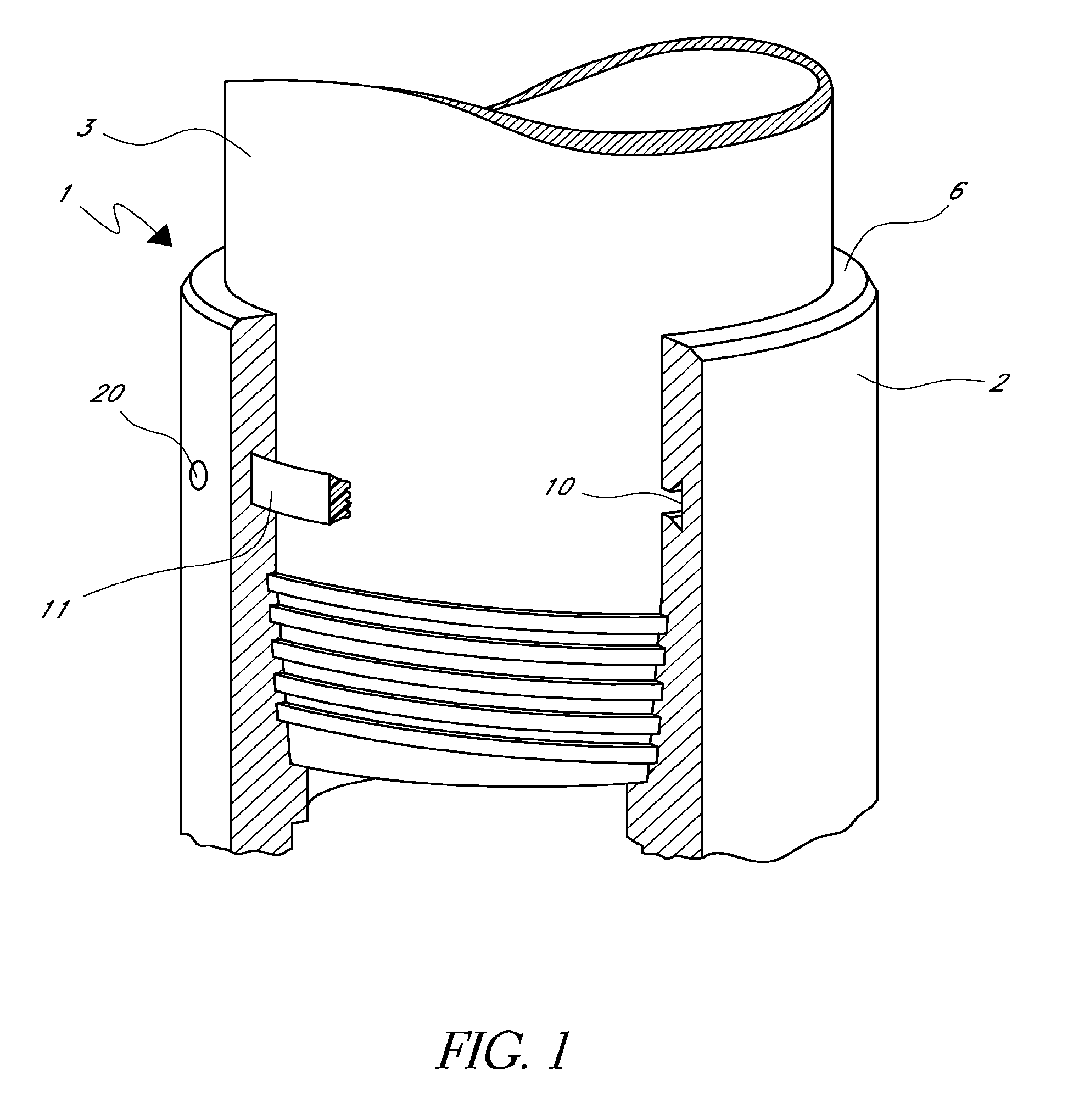
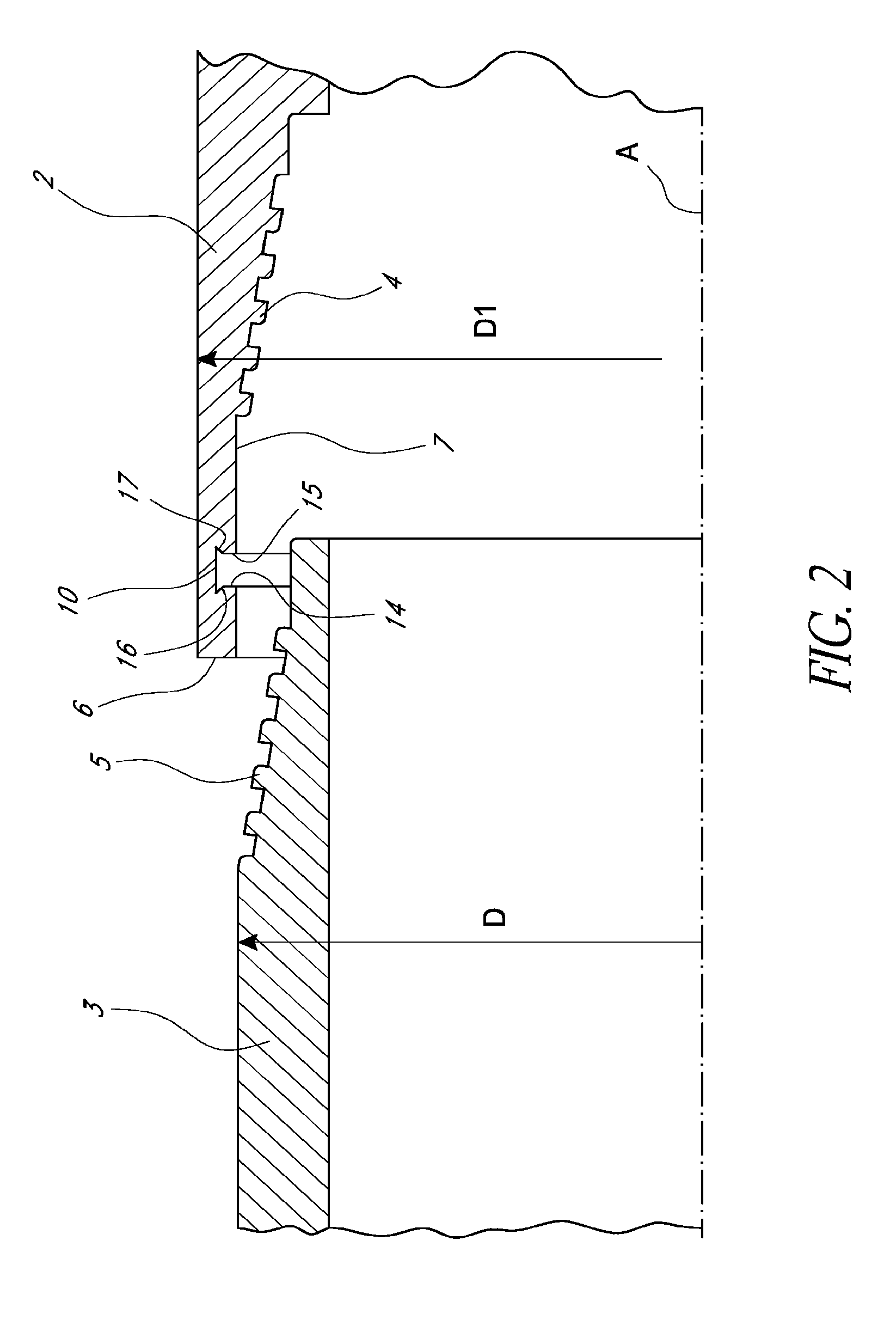
[0031]With particular reference to the figures, there is shown a threaded joint indicated overall by reference numeral 1, connecting two tubes, a male tube 3, also called a pin, with a nominal external diameter D, and a female pipe 2, also called a box, of external diameter D1.

[0032]The pin 3 has a threaded portion 5, with male threads of appropriate profile, e.g. trapezoidal, and the box 2 has an internal threaded portion 4 with female threads. The common axis of the pipe and the pin and box is indicated by A.

[0033]The box 2 ends with a nose 6. The portion of the box 2 close to the nose 6 comprises a non-threaded surface 7.

[0034]Preferably, but not necessarily, the joint 1 has an internal metal-to-metal seal between the pin nose 6′ of the pin 3 and box shoulder 8.

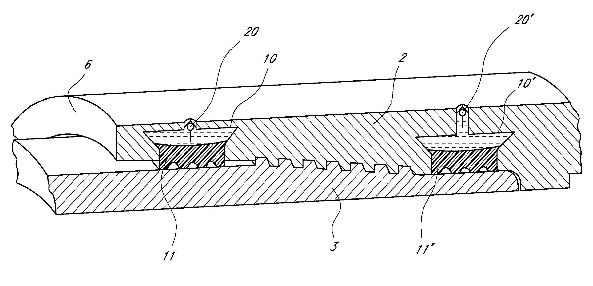
[0035]With particular reference to the embodiment of FIG. 1, there is provided a housing configured as an annular groove 10 in the box 2 between the end of the thread 4 and the nose 6. The groove 10 houses a ring 11 formin...


PUM


Abstract

A threaded joint comprises a pin coupled to a box with an annular groove, one or a pair of seal rings, and hydraulic actuating means to pressurize the seal ring or rings against the pin to provide sealability of the joint. The seal ring or rings comprise a frustoconical surface, an external surface, and an internal surface with one or more protruding annular ribs. In the unpressurized state, the seal ring or rings do not protrude from the groove. In the pressurized state, the frustoconical surface of the sealing ring is in sealing contact with an internal surface of the annular groove of the box, and the annular ribs of the sealing ring are in sealing contact with the external surface of the pin.

Description

CROSS-REFERENCE TO RELATED APPLICATIONS[0001]This application is a U.S. National Phase of the PCT International Application No. PCT / EP2008 / 058073, filed Jun. 25, 2008 and published as WO 2009 / 000851 on Dec. 31, 2008, which claims priority to European Application No. 07111204.9, filed Jun. 27, 2007. The disclosure of both prior applications is incorporated by reference in their entirety and should be considered a part of this specification.FIELD OF THE INVENTION[0002]The present invention relates to threaded joints, in particular for connecting tubes to create strings used in the hydrocarbon industry especially for use in the field of OCTG (Oil Country Tubular Goods) and pipelines in offshore applications.BACKGROUND OF THE INVENTION[0003]Searching for oil or, more generally, hydrocarbons has become more demanding in terms of hardware and devices in recent years because oil and gas fields or reservoirs are located deeper or in places difficult to reach and below the sea. Prospecting f...

Claims


Application Information

Patent Timeline
Patent Type & Authority Patents(United States)
IPC IPC(8): F16L17/00F16L25/00
CPCE21B17/042F16L17/10F16L15/003
Inventor SANTI, NESTOR J.MAZZAFERRO, GASTONQUIROGA, ALFREDO
Owner TENARIS CONNECTIONS
Why Eureka
Try Eureka