Continuous semi-dense pneumatic conveying system and method

a conveying system and semi-dense technology, applied in the direction of conveyors, conveyors, transportation and packaging, etc., can solve the problems of high capital and operating costs significant non-product conveying time involved, and other drawbacks of dense phase conveying systems, so as to reduce air velocity, reduce capital costs, and high solids loading

Inactive Publication Date: 2012-12-25
MAGNUM SYST
View PDF21 Cites 24 Cited by
  • Summary
  • Abstract
  • Description
  • Claims
  • Application Information

AI Technical Summary

Benefits of technology

[0012]The present invention is directed to a continuous semi-dense phase conveying system which has a high solids loading, lower air velocities, and low capital costs. In general, the continuous semi-dense phase conveying system comprises a vessel having a gas inlet, a particulate material inlet, and a gas and particulate material outlet. The vessel has a pressure therein during operation of about 15 psig or less. A rotary airlock valve is coupled to the particulate material inlet for continuously feeding particulate material into the particulate material inlet of the vessel. A pressurizing gas supply line is coupled to a pressurized gas source and branches into at least a feed gas line and a bypass line. The feed gas line provides pressurizing gas to the vessel at the gas inlet, and the bypass line has a bypass control valve and is coupled to the pneumatic conveying line, which is coupled to the gas and particulate material outlet of the vessel. Fluidizing gas lines may be coupled to the bypass line.

Problems solved by technology

Because air compressors and ASME code equipment must be used in order to achieve and withstand the high conveying pressures, dense phase systems have dramatically increases the capital and operating cost of the system compared to that of dilute phase systems.
Dense phase conveying systems suffer from other drawbacks.
Thus, a major disadvantage associated with batch dense phase conveying systems is that there is a significant amount of non-product conveying time involved while the pressure containment vessel is venting, being refilled, and pressurized.
Another disadvantage is that, because of the significant amount of non-conveying time, the conveying pipe size must be relatively large to compensate for the lost time.
Another disadvantage is that the last portions of the particulate material leaving the pressure containment vessel tend to accelerate rapidly as the material conveying pipe is blown free and the high pressure gas seeks to dissipate down along the material conveying pipe.
The increased acceleration of the particulate material being conveyed often causes a significant amount of product degradation to the last portion of the particulate material being conveyed.
However, blow-pot systems still run in batch mode and have significant non-conveying time.
Because of the high pressures used to move material, the equipment utilized must meet ASME code requirements, and air compressors must be utilized, resulting in high capital costs.

Method used


Image

  • Continuous semi-dense pneumatic conveying system and method
  • Continuous semi-dense pneumatic conveying system and method

Examples


example 1

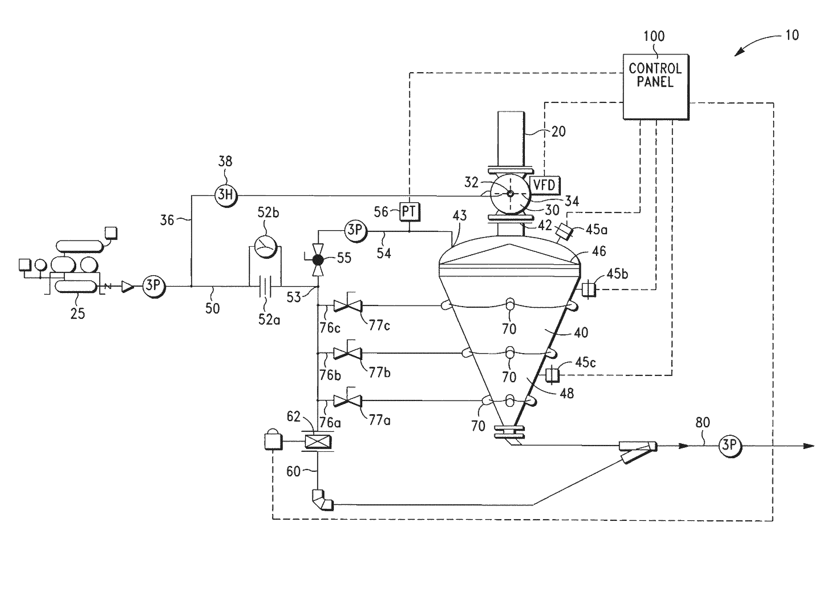
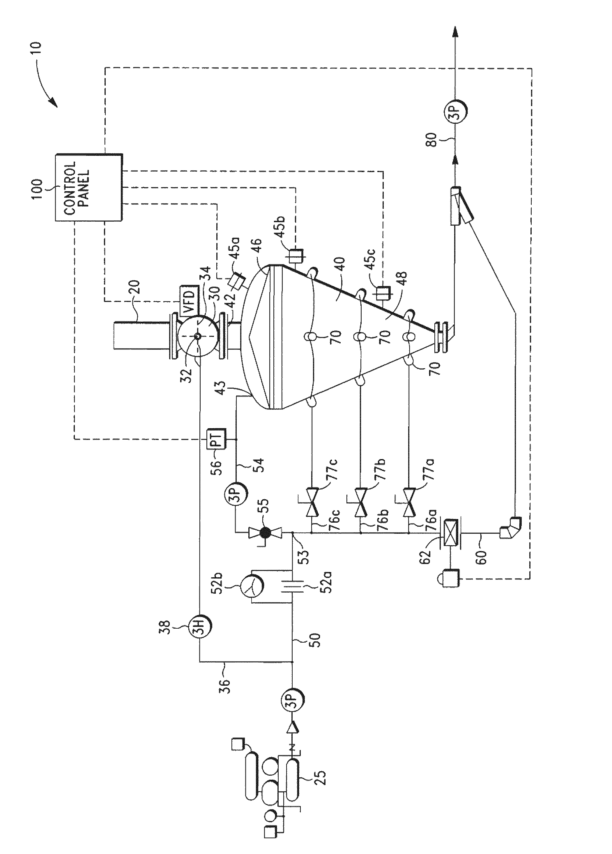
[0034]In this example, the continuous semi-dense phase conveying system of the present invention was compared to a continuous dilute phase system and a batch dense phase system. For all of the systems, the conveying line comprised 260 feet of 3-inch tube or pipe with seven 90-degree 36-inch centerline radius elbows followed by four Smoot 3-inch tube slide diverters (Magnum Systems, Kansas City, Kans.) with approximately three feet of 688SB flexible material handling hose (Gates Corporation, Denver, Colo.) per slide diverter. The continuous semi-dense phase conveying system of the present invention and the dilute phase system were comprised of 3-inch aluminum tubing (2.76 ID), while the batch dense phase system was comprised of 3-inch ASME-code carbon steel pipe (3.05 ID).

[0035]For the continuous semi-dense conveying system, particulate material is loaded into a 24 ft3 / day scale hopper with an Advantage Lite load cells at 0, 120, and 240 degrees mounted to the floor (Hardy Instrument...


PUM


Abstract

A continuous semi-dense phase conveying system comprising a vessel having a gas inlet, a particulate material inlet, and a gas and particulate material outlet, which has an operating pressure of about 15 psig or less. The system includes a rotary airlock valve for feeding particulate material into the vessel and a pressurizing gas supply which branches into a feed gas line and a bypass line. A pneumatic conveying line coupled to the gas and particulate material outlet of said the and coupled to the bypass line. The pressure of the vessel is controlled using a bypass valve on said bypass line and optimize the flow of gas and particulate matter through the pneumatic conveying line.

Description

CROSS-REFERENCE TO RELATED APPLICATIONS[0001]Not applicable.STATEMENT REGARDING FEDERALLY SPONSORED RESEARCH OR DEVELOPMENT[0002]Not applicable.BACKGROUND OF THE INVENTION[0003]1. Field of the Invention[0004]The invention relates to a conveying method and apparatus for conveying large quantities of dry bulk materials through a material conveying pipe.[0005]2. Description of Related Art[0006]Pneumatic conveying systems are designed to move large quantities of particulate material in an air (or other inert gas) medium through a material conveying pipe. Pneumatic conveying systems are of two general types: dilute phase systems and dense phase systems. Typically, the type of the particulate material to be conveyed determines what type of pneumatic conveying system to utilize.[0007]In dilute phase conveying systems, particulate material is metered into the conveying pipe from a hopper or other holding device. A standard blower delivers a high volume of air (or inert gas) at a low pressur...

Claims


Application Information

Patent Timeline
Patent Type & Authority Patents(United States)
IPC IPC(8): B65G53/12
CPCB65G53/46B65G53/66
Inventor SCHULTZ, BRAD
Owner MAGNUM SYST
Why Eureka
Try Eureka