Optical level detector for a beverage machine

a technology of optical level detection and beverage machine, which is applied in the direction of liquid/fluent solid measurement, machine/engine, and investigating moving fluids/granular solids. it can solve the problems of increasing the complexity of the connection of the emitter-detector to the control unit, complicating the cleaning of such cavities, and complicating the arrangement of the light emitter and the detector

Active Publication Date: 2012-12-25
SOC DES PROD NESTLE SA
View PDF14 Cites 24 Cited by
  • Summary
  • Abstract
  • Description
  • Claims
  • Application Information

AI Technical Summary

Benefits of technology

[0009]The present invention thus provides an optical level detector that alleviates at least some of the prior art drawbacks. This is achieved by providing a level detector that includes a light emitter for emitting a light beam through the cavity of a reservoir containing a liquid, typically water, the level or upper surface of which is to be monitored. The level detector further has a light detector and a beam deflection arrangement for deflecting the emitted light beam onto or away from the light detector. In order to be able to maintain the light emitter and light detector relatively close together while avoiding protruding or intrusive prism elements extending into the cavity, the beam deflection arrangement is based on: a light refraction principle that changes the path of the beam depending on the position of the surface of the liquid in the cavity; and a reflection or mirror principle that reflects the emitted beam generally the light detector.
[0023]To simplify cleaning of the cavity, for instance for removing scale, the cavity of the reservoir can be convex. Avoiding additional edges within the cavity also reduces local accumulation of scale along such edges.
[0024]The level detection device of the invention thus permits the use of a simplified configuration and connection of the emitter and detector, i.e. directly on a PCB adjacent the reservoir without having to provide a complex connection arrangement for the emitter and / or detector around the reservoir and / or at distant locations of the reservoir, and without having to provide non-convex cavity, e.g. resulting from the use of an additional component extending into the cavity such as a refractor prisms, like in the above cited prior art.
[0026]A reflection surface(s) may be located outside the cavity of the reservoir and optionally it can form an outside surface of the bottom wall or of a sidewall. This configuration is advantageous to avoid exposure of the reflection surface(s) to the liquid contained in the cavity and thus it reduces wear and need for cleaning, especially when the liquid is not water but for example syrup or another concentrate.
[0029]In one embodiment, the emitter and the detector are located along a reservoir sidewall, at least one of such reflection surface(s) being located on the bottom wall or a top wall of the reservoir. In this case, a light beam can be directed from a sidewall to the bottom or top of the receptacle and then reflected back from the bottom or top to the sidewall. For instance, the emitter, the detector and such reflection surface(s) can be located adjacent a top corner or the bottom corner of the cavity formed by a sidewall and a top wall or a bottom wall, respectively. This reduces the length of the path of the light beam through the reservoir and reduces problems of positioning tolerances and unwanted deviations of the light beam.

Problems solved by technology

A problem with these embodiments resides in the fact that the emitter and detector are located on different faces of the reservoir which complicates the arrangement of the light emitter and detector and connections thereof to a control unit, in particular to a printed circuit board whose shape will normally not follow the shape of the angled section or corner about which emitter and detector are placed.
A problem with this approach resides in the fact that the emitter and detector are mounted in a movable component of the beverage maker, which involves complications with the connection between the emitter, detector and the fixed control unit of the beverage maker.
Moreover, such a emitter-detector arrangement operating with a reflection on the liquid surface can hardly be located anywhere else than above the surface which also increases the complexity of the connections of the emitter-detector to a control unit.
A problem with this embodiment lies in the fact that the triangular refractor protrudes into the liquid in the reservoir and is directly exposed thereto and thus requires occasional cleaning, including for removing scale deposits.
Moreover, this triangular refractor protruding inside the cavity of the reservoir i.e. rendering the cavity of the reservoir non-convex, complicates the cleaning of such cavity.

Method used


Image

  • Optical level detector for a beverage machine
  • Optical level detector for a beverage machine
  • Optical level detector for a beverage machine

Examples


Embodiment Construction

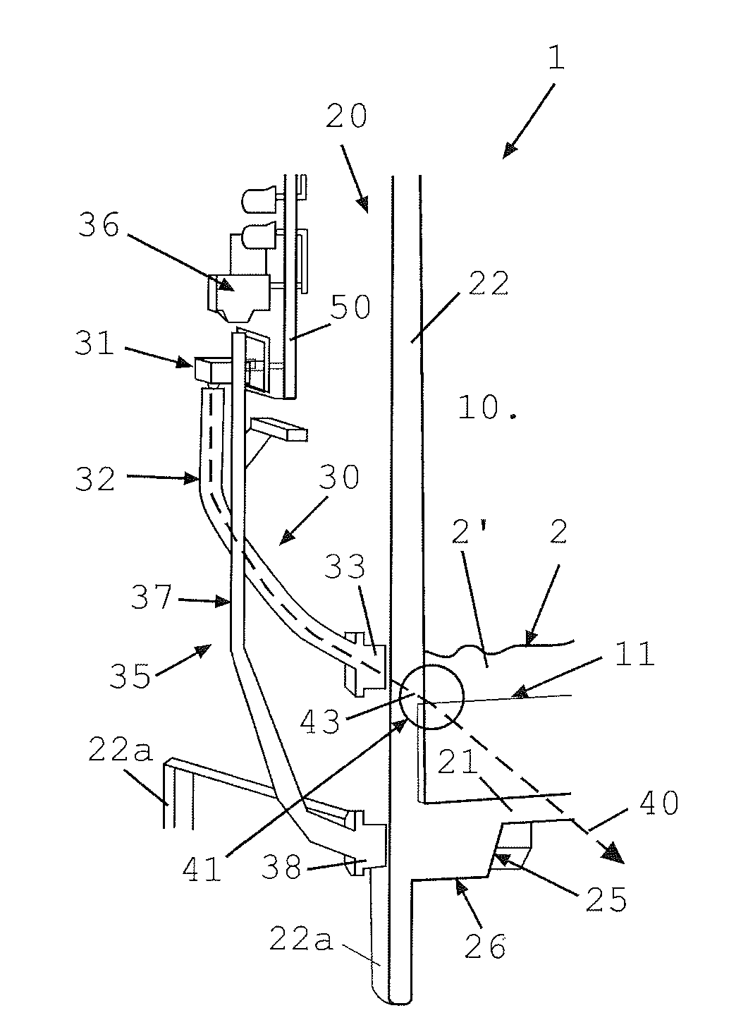
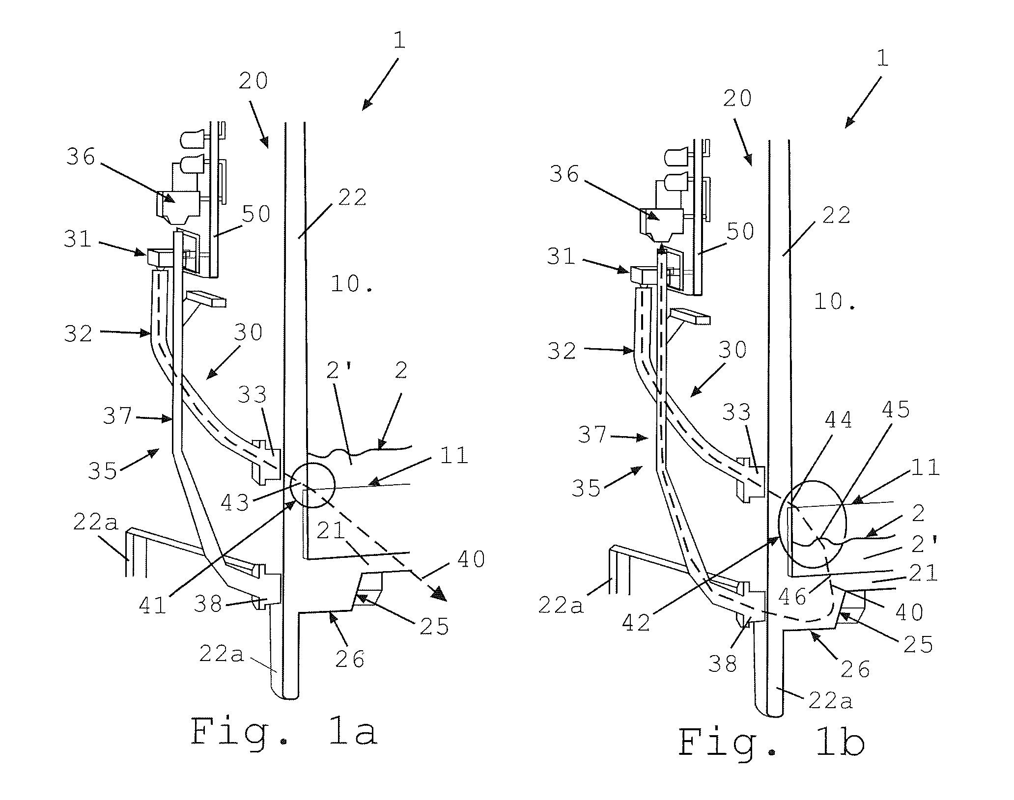
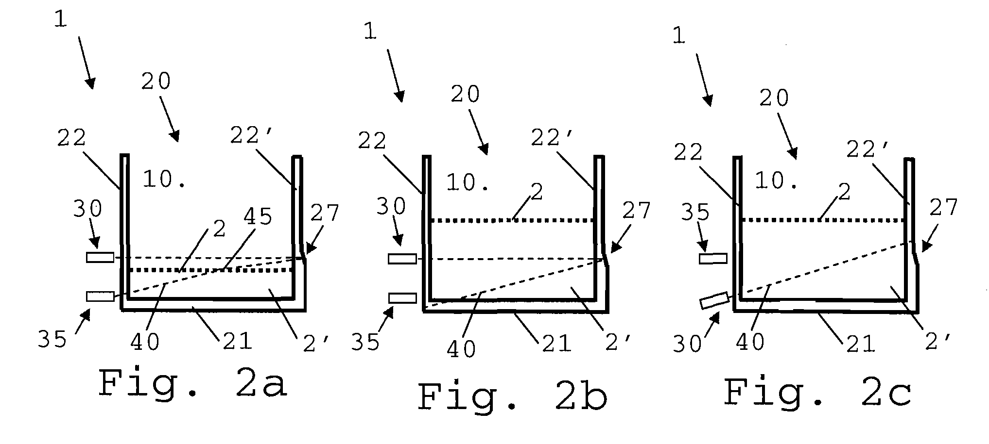
[0040]FIGS. 1a and 1b show part of a perspective view of a level detection device 1 for detecting a level or upper surface 2 of a liquid 2′ contained in a cavity 10 at a reference level 11.

[0041]Device 1 has a reservoir 20 with a bottom wall 21 and one or more sidewalls 22 extending from bottom wall 21 for delimiting cavity 10. Sidewalls 22 are provided with feet 22a for supporting reservoir 20.

[0042]A light emitter 30 for emitting a light beam 40 towards and into cavity 10 has: a light source 31 typically of the IR type or a LED; a light guide 32 for guiding light emitted by light source 31 into one end of guide 32; and, at the other end of guide 32, an output 33 adjacent sidewall 22 of reservoir 20. Emitter 30 is so located and oriented adjacent wall 22 of reservoir 20 that light beam 40 enters at an non-perpendicular angle into cavity 10.

[0043]Reservoir 20 is made of material transparent to light beam 40 so that output 33 delivers light beam 40 into cavity 10 via sidewall 22.

[004...


PUM

PropertyMeasurementUnit
refractionaaaaaaaaaa
reflectionaaaaaaaaaa
angleaaaaaaaaaa

Abstract

A level detection device for detecting an upper surface of a liquid at a reference level. The device includes a reservoir having a bottom wall and one or more side walls that delimit a cavity for containing the liquid; a light emitter for emitting a light beam towards this cavity; at least one reflection surface for reflecting the light beam; and a light detector for detecting the emitted light beam upon reflection. The emitter and detector are so arranged that, when the surface of the liquid passes the reference level, a state of detection of the light beam by the detector is changed. The emitter, detector and reflection surface(s) are so located and oriented relative to the cavity that the emitted light beam is: detectable by the detector upon travelling through the liquid in the cavity; and refractable at the surface of the liquid towards or away from the detector so that the state of detection is a function of such refraction.

Description

FIELD OF THE INVENTION[0001]The field of the invention pertains to the optical level detection of a liquid in a reservoir, in particular a reservoir of a liquid food or beverage preparation machines. For the purpose of the present description, a “beverage” is meant to include any liquid food, such as tea, coffee, hot or cold chocolate, milk, soup, baby food, etc.BACKGROUND ART[0002]Certain beverage or food preparation machines use capsules containing ingredients to be extracted or to be dissolved; for other machines, the ingredients are stored and dosed automatically in the machine or else are added at the time of preparation of the drink.[0003]Most coffee machines possess filling means that include a pump for liquid, usually water, which pumps the liquid from a source of water that is cold or indeed heated through heating means, such as a heating resistor, a thermoblock or the like.[0004]Most beverage machines have a reservoir for containing and for the supply of a constituent of t...

Claims


Application Information

Patent Timeline
Patent Type & Authority Patents(United States)
IPC IPC(8): G01N15/06G01N21/49G01N21/85
CPCG01F23/2925G01F23/2921Y10T137/8158
Inventor LANG, MARKUSMORI, PETERMOSER, RENZO
Owner SOC DES PROD NESTLE SA
Why Eureka
Try Eureka