Filtering device and differential signal transmission circuit capable of suppressing common-mode noises upon transmission of a differential signal

a filtering device and differential signal technology, applied in the direction of cross-talk reduction, line-transmission details, waveguides, etc., can solve the problems of not being miniaturized, its performance will be degraded, and the differential signal may accompany unwanted common-mode noises, so as to achieve the effect of suppressing common-mode noises and negative permittivity

Active Publication Date: 2012-12-25
NAT TAIWAN UNIV
View PDF2 Cites 16 Cited by
  • Summary
  • Abstract
  • Description
  • Claims
  • Application Information

AI Technical Summary

Benefits of technology

[0007]Therefore, the object of the present invention is to provide a filtering device and a differential signal transmission circuit that can overcome the aforesaid drawbacks associated with the prior art.
[0008]According to one aspect of this invention, there is provided a filtering device capable of suppressing common-mode noises upon transmission of a differential signal. The filtering device comprises a differential transmission line, a grounding layer, a dielectric unit and a conductive structure. The differential transmission line has a pair of conductive traces spaced apart from each other. The grounding layer is spaced apart from the differential transmission line. The dielectric unit is disposed between the differential transmission line and the grounding layer. The conductive structure is embedded in the dielectric unit, is coupled electrically to the conductive traces and the grounding layer, and cooperates with the differential transmission line, the grounding layer and the dielectric unit to form a stacked structure that has an effective negative permittivity, thereby suppressing the common mode noises coupled to the conductive traces.

Problems solved by technology

However, a differential signal may accompany unwanted common-mode noises.
Although each of the aforesaid filtering devices has a relatively low cost, and is advantageous in terms of common-mode noises suppression over a wideband frequency range, it is disadvantageous in the following ways: a) it can not be miniaturized because one of the length and the width of the patterned grounding structure must be one half or one quarter of the wavelength of the differential signal, and b) its performance will be degraded with the inclusion of a shielding structure beneath the patterned ground structure.

Method used


Image

  • Filtering device and differential signal transmission circuit capable of suppressing common-mode noises upon transmission of a differential signal
  • Filtering device and differential signal transmission circuit capable of suppressing common-mode noises upon transmission of a differential signal
  • Filtering device and differential signal transmission circuit capable of suppressing common-mode noises upon transmission of a differential signal

Examples


Embodiment Construction

[0028]Before the present invention is described in greater detail with reference to the accompanying preferred embodiments, it should be noted herein that like elements are denoted by the same reference numerals throughout the disclosure.

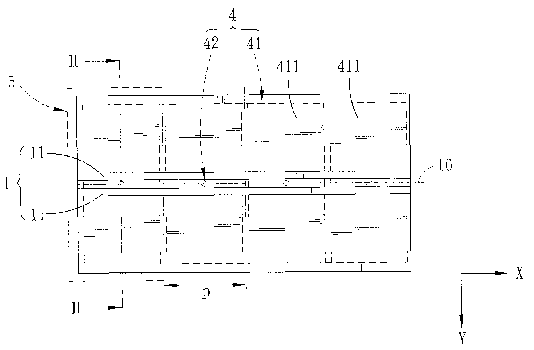
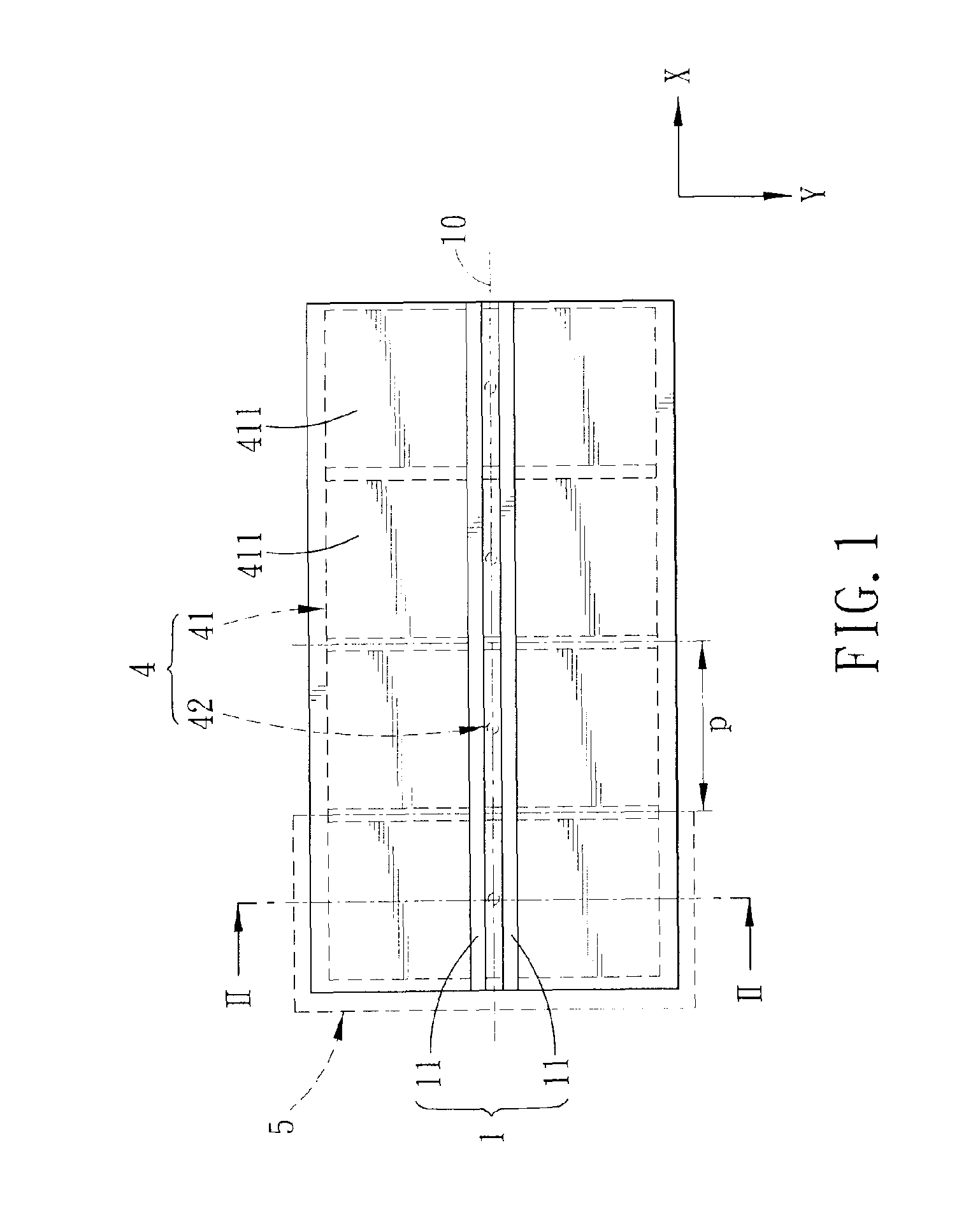
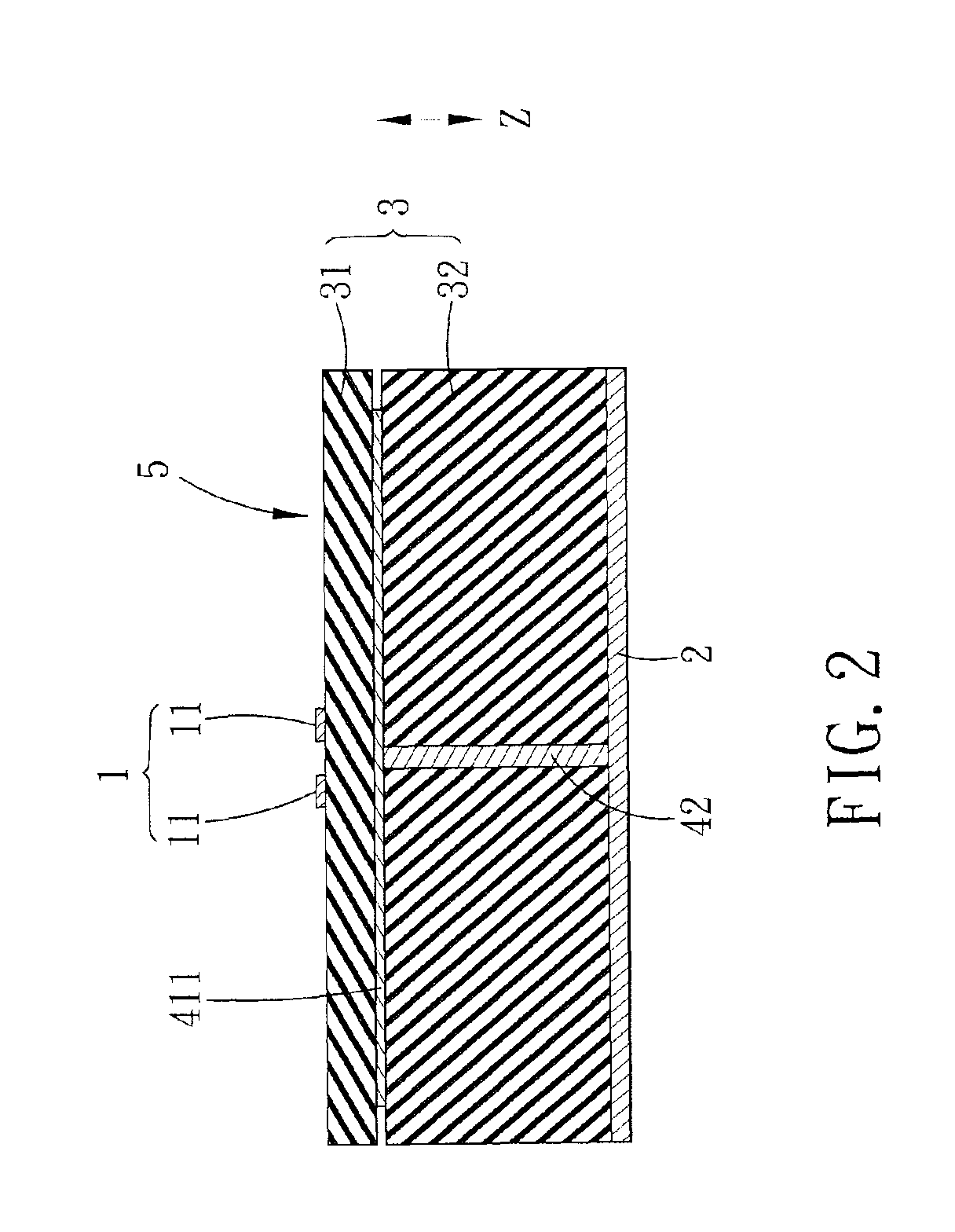
[0029]Referring to FIGS. 1 and 2, the first preferred embodiment of a filtering device capable of suppressing common-mode noises upon transmission of a differential signal according to this invention is shown to include a differential transmission line 1, a grounding layer 2, a dielectric unit 3 and a conductive structure 4. In this embodiment, the filtering device can be implemented in a three-layer printed circuit board (PCB).

[0030]The differential transmission line 1 has a pair of conductive traces 11 spaced apart from each other and symmetrical with respect to a centerline 10 defined therebetween and extending in a first direction (X). In this embodiment, the conductive traces 11 extend in the first direction (X), and are opposite to each other ...


PUM


Abstract

A filtering device is capable of suppressing common mode noises upon transmission of a differential signal, and includes a differential transmission line, a grounding layer, a dielectric unit and a conductive structure. The differential transmission line has a pair of conductive traces spaced apart from each other. The grounding layer is spaced apart from the differential transmission line. The dielectric unit is disposed between the differential transmission line and the grounding layer. The conductive structure is embedded in the dielectric unit, is coupled electrically to the conductive traces and the grounding layer, and cooperates with the differential transmission line, the grounding layer and the dielectric unit to form a stacked structure that has an effective negative permittivity, thereby suppressing the common mode noises coupled to the conductive traces. A differential signal transmission circuit is also disclosed.

Description

CROSS-REFERENCE TO RELATED APPLICATION[0001]This application claims priority of Taiwanese Application No. 098126758, filed on Aug. 10, 2009.BACKGROUND OF THE INVENTION[0002]1. Field of the Invention[0003]This invention relates to a filtering device and a differential signal transmission circuit, more particularly to a filtering device and a differential signal transmission circuit capable of suppressing common-mode noises upon transmission of a differential signal.[0004]2. Description of the Related Art[0005]Differential signal transmission has been widely used in high-speed digital systems. However, a differential signal may accompany unwanted common-mode noises. For a high-speed data link, a cable is necessary to transmit the differential signal between two different electronic apparatuses. When the common-mode noises are coupled to the cable, the cable is excited to behave as an electromagnetic interference (EMI) antenna. Therefore, suppressing the common-mode noises upon transmi...

Claims


Application Information

Patent Timeline
Patent Type & Authority Patents(United States)
IPC IPC(8): H01P3/08H04B3/32
CPCH01P1/203
Inventor WU, TZONG-LINTSAI, CHUNG-HAO
Owner NAT TAIWAN UNIV
Why Eureka
Try Eureka