Display device, terminal device, light source device, and optical member having a light-direction restricting element and a transparent/scattering state switching element

a technology of light-direction restricting elements and optical components, which is applied in the direction of optical elements, lighting and heating apparatus, instruments, etc., can solve the problems of severe reduction of display quality, difficulty in a third party's view, and difficulty in a third party's presence, so as to reduce the moiré and increase the directivity of the display

Active Publication Date: 2012-12-25
NEC CORP +1
View PDF23 Cites 10 Cited by
  • Summary
  • Abstract
  • Description
  • Claims
  • Application Information

AI Technical Summary

Benefits of technology

[0018]An object of the present invention is to provide a display device capable of reducing moiré in a display device having increased display directivity, to provide a terminal device that uses the display device, and to provide a light source device and optical member that are incorporated into the display device.

Problems solved by technology

It is thereby impossible or extremely difficult for a third party present beside the user to see from the side or read the various types of information displayed when the anti-eavesdropping device is mounted on the liquid crystal display of the information display.
However, the anti-eavesdropping device described in Prior Art 1 has such problems as those described below.
Specifically, when the anti-eavesdropping device described in Prior Art 1 is attached to the display device, moiré occurs to a significant degree between the pixels of the display device and the colored silicone rubber sheets constituting the anti-eavesdropping device, and the display quality is severely reduced.
However, the above-described conventional technique has such problems as those described below.
However, moiré still occurs, and the moiré-reducing effects are inadequate.
It is therefore impossible to adequately reduce moiré even when the control film is placed in a tilted position.
In this case, when the tilt angle of the control film is increased in order to reduce moiré, the direction in which the light is restricted, specifically, the direction in which eavesdropping is prevented, is tilted from the horizontal direction, thus creating discomfort for the user.

Method used


Image

  • Display device, terminal device, light source device, and optical member having a light-direction restricting element and a transparent/scattering state switching element
  • Display device, terminal device, light source device, and optical member having a light-direction restricting element and a transparent/scattering state switching element
  • Display device, terminal device, light source device, and optical member having a light-direction restricting element and a transparent/scattering state switching element

Examples


first embodiment

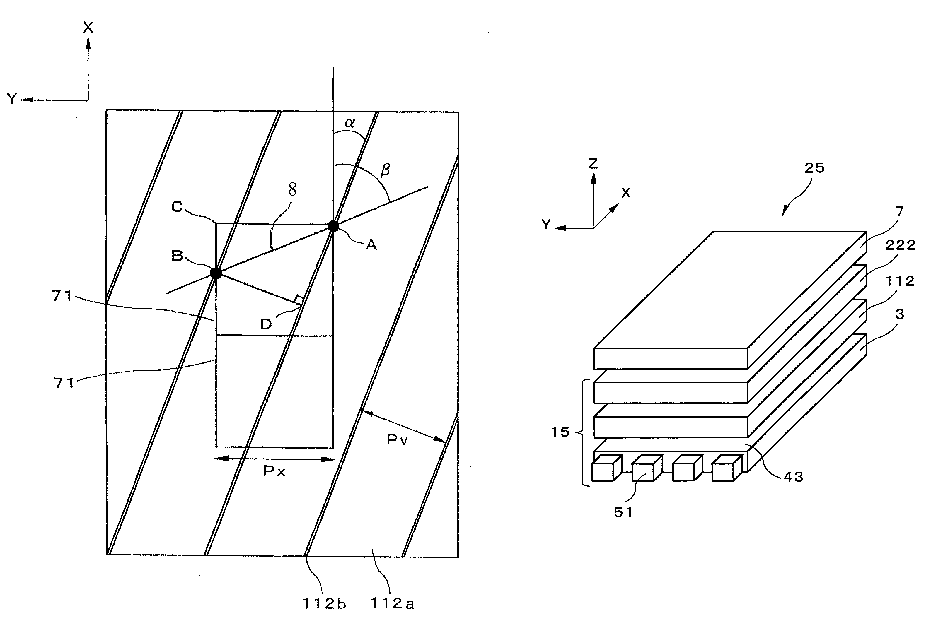
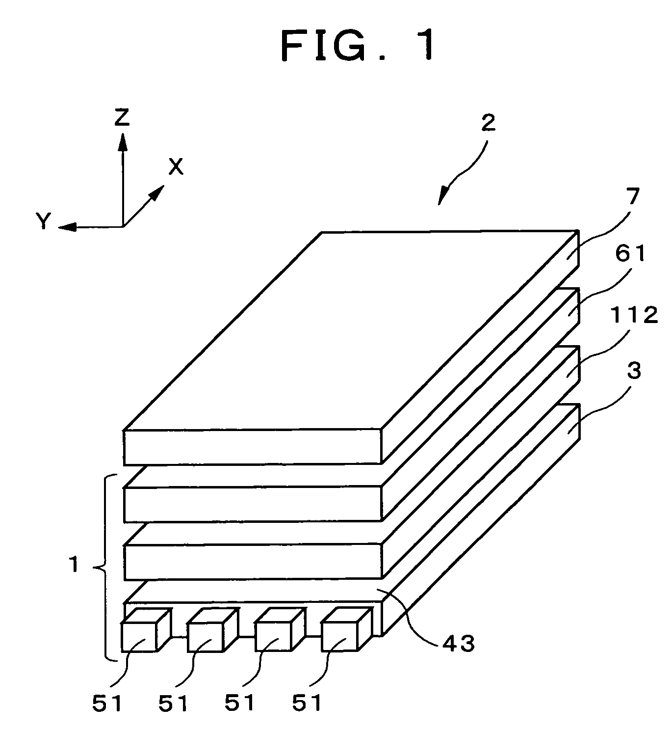
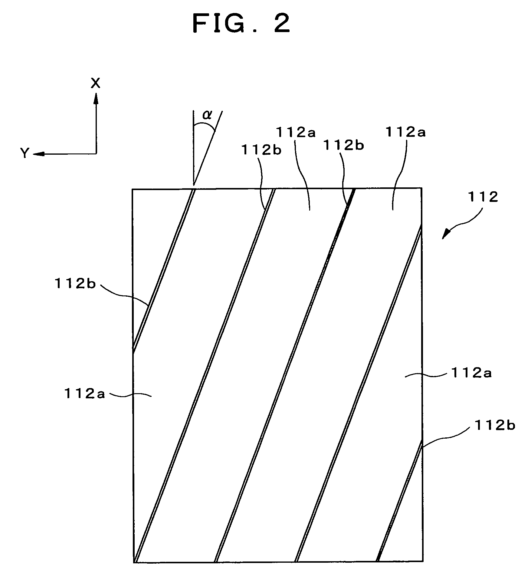
[0068]The display device, terminal device, light source device, and optical member according to embodiments of the present invention will be described in detail hereinafter with reference to the accompanying drawings. The display device, terminal device, light source device, and optical member according to the present invention will first be described. FIG. 1 is a perspective view showing the display device according to the present embodiment; FIG. 2 is a top view showing a louver as the light-direction restricting element of the display device shown in FIG. 1; FIG. 3 is a top view showing the anisotropic scattering sheet of the display device shown in FIG. 1; FIG. 4 is a top view showing the relationship between the light-restricting direction of the louver and the scattering direction of an anisotropic diffusion sheet; and FIG. 5 is a perspective view showing the terminal device according to the present embodiment.

[0069]As shown in FIG. 1, a light source device 1 is provided in th...

second embodiment

[0114]Furthermore, in the same manner as in the aforementioned second embodiment, the thickness of the display device can be reduced since the anisotropic scattering sheet is not provided in the present embodiment. Furthermore, the anisotropic scattering unit, the louver, and the transmissive liquid crystal panel are optically bonded. Therefore, interference fringes from air layers can be prevented from occurring, and the display quality can be enhanced even further. The louver is also provided on the user side of the display panel, and anisotropic scattering structures are formed in this louver. The user can therefore easily attach and detach a louver equipped with an anisotropic scattering structure according to the situation.

[0115]A fourth embodiment of the present invention will next be described. FIG. 15 is a perspective view showing the display device according to the present embodiment; and FIG. 16 is a perspective view showing the anisotropic scattering sheet of the display ...

fourth embodiment

[0118]An example was described in the fourth embodiment and modification thereof in which a prism sheet or lenticular lens is provided separately from the louver, but the one-dimensionally arranged prism structures 641 may be formed directly on the surface of the louver, and the cylindrical lenses 651 may also be formed directly on the surface of the louver.

[0119]A fifth embodiment of the present invention will next be described. FIG. 18 is a sectional view showing the display device according to the present embodiment; and FIG. 19 is a sectional view showing the transparent / scattering state switching element in the display device shown in FIG. 18. As shown in FIG. 18, the display device 24 of the present embodiment differs from that of the first embodiment in that a transparent / scattering state switching element 122 is provided between the anisotropic scattering sheet 61 and the transmissive liquid crystal panel 7. Through the switching operation of the transparent / scattering state...


PUM

PropertyMeasurementUnit
angleaaaaaaaaaa
angleaaaaaaaaaa
angleaaaaaaaaaa

Abstract

A display device comprising a light source and having an optical waveguide, a louver, an anisotropic scattering sheet, and a transmissive liquid crystal panel disposed along the path of light emitted from the light source. The light-restricting direction of the louver is tilted at an angle α from the Y-axis direction. The value of the angle α is set so that the arrangement direction of moiré created between the louver and the liquid crystal panel approaches the X-axis direction. A plurality of belt-shaped convex portions extending in the Y-axis direction are formed on the surface of the anisotropic scattering sheet, and are configured so that the scattering direction of the light has anisotropy. Specifically, scattering in the X-axis direction is increased, and scattering in the Y-axis direction is reduced. Moiré can thereby be reduced in a display device having increased directivity of the display.

Description

BACKGROUND OF THE INVENTION[0001]1. Field of the Invention[0002]The present invention relates to a display device in which the directivity of the display is increased with respect to a specific direction, to a terminal device provided with this display device, and to a light source device and optical member incorporated into the aforementioned display device.[0003]2. Description of the Related Art[0004]Due to recent advances in technology, display panels have been deployed in a range of devices that includes monitors, television sets, and other large terminal devices; notebook-type personal computers, cash dispensers, vending machines, and other mid-sized terminal devices; and personal TVs, PDAs (Personal Digital Assistance: personal information terminal), mobile telephones, mobile gaming devices, and other small terminal devices that are used in a variety of locations. Because of their thin profile, light weight, small size, low energy consumption, and other advantages, display dev...

Claims


Application Information

Patent Timeline
Patent Type & Authority Patents(United States)
IPC IPC(8): G02F1/1335F21V17/02F21V7/04
CPCG02B6/0036G02B6/0038G02F1/133524G02F1/133606F21V5/002F21V9/00G02B5/02G02F1/133504G02F2201/44
Inventor UEHARA, SHIN-ICHINIIOKA, SHINYAIMAI, MASAO
Owner NEC CORP
Why Eureka
Try Eureka