
Seat cushion with bubble elements

a seat cushion and element technology, applied in the field of seat cushions, can solve the problems of slowed seat production, high risk of individual air bubble displacement or air supply disruption, and disadvantageous assembly complexity, and achieve the effect of low stability of the carrier elemen

Inactive Publication Date: 2013-01-01
FS FEHRER AUTOMOTIVE GMBH
View PDF5 Cites 80 Cited by
  • Summary
  • Abstract
  • Description
  • Claims
  • Application Information

AI Technical Summary

Benefits of technology

The present invention aims to provide a seat cushion with air bubbles that can be easily assembled and positioned without displacing the bubbles or damaging the air inlet. The invention solves the problem of integrating a head rest into a seat design by providing a flat and lightweight seat that still adapts to the individual seating position in the head region. It also employs bubble elements that provide improved stability and evenly distributed supporting effect, reducing the required stability of the carrier element. Overall, the invention improves the quality and performance of sports seats while achieving a balance between stability and comfort.

Problems solved by technology

In this context, however, the complexity in terms of assembly is disadvantageous, since all individual air bubbles are separately mounted on one carrier and the seat cushion is subsequently disposed thereon.
The assembly process of the seat cushion, however, involves the high risk that individual air bubbles may be displaced or air supply may be disrupted.
As a consequence, seat production is slowed down and in some instances requires disassembly for rectification of malpositions or damage to the air distribution system.

Method used


Image

  • Seat cushion with bubble elements
  • Seat cushion with bubble elements
  • Seat cushion with bubble elements

Examples


Embodiment Construction

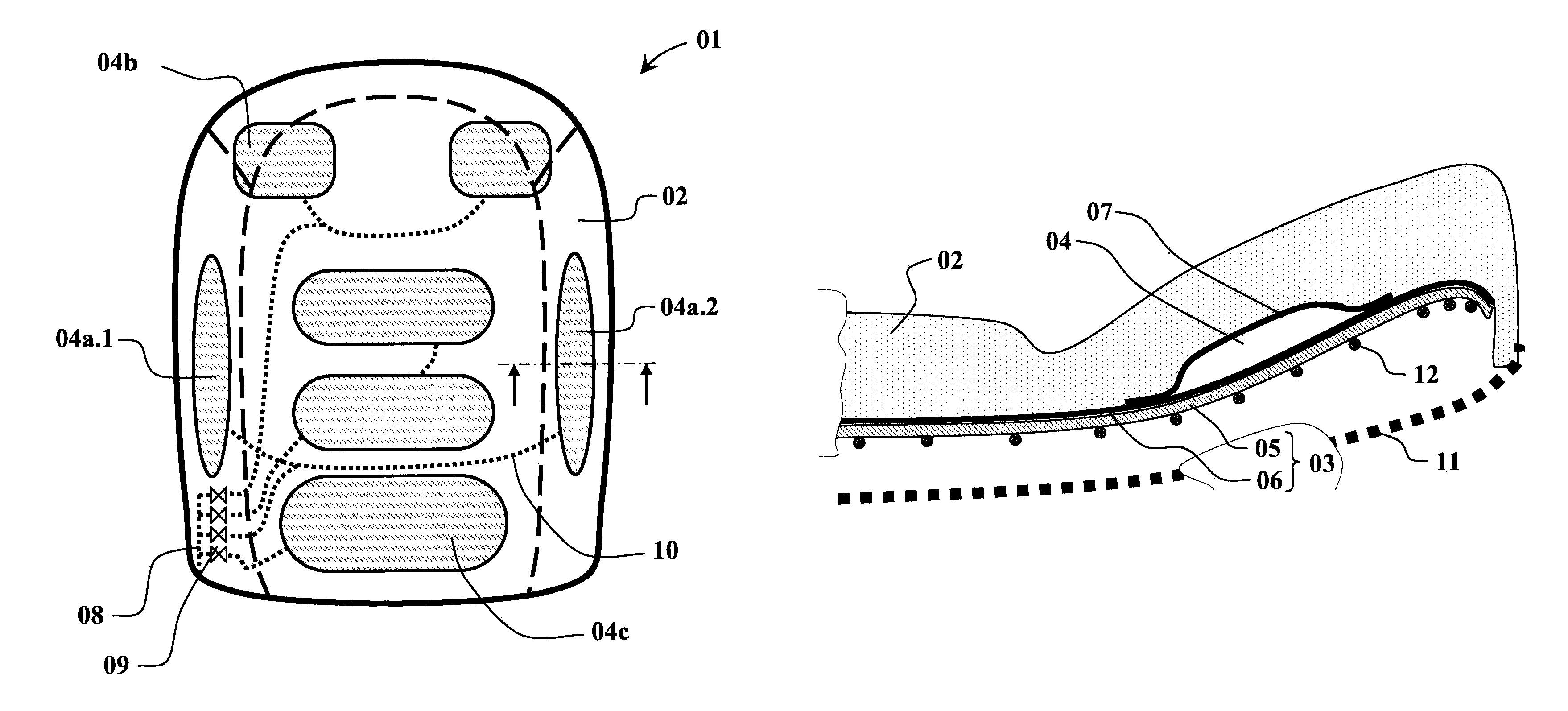
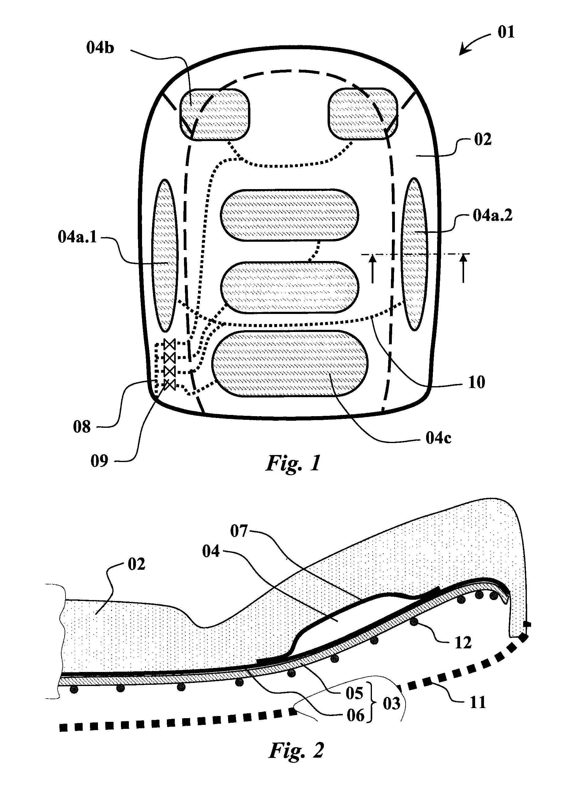
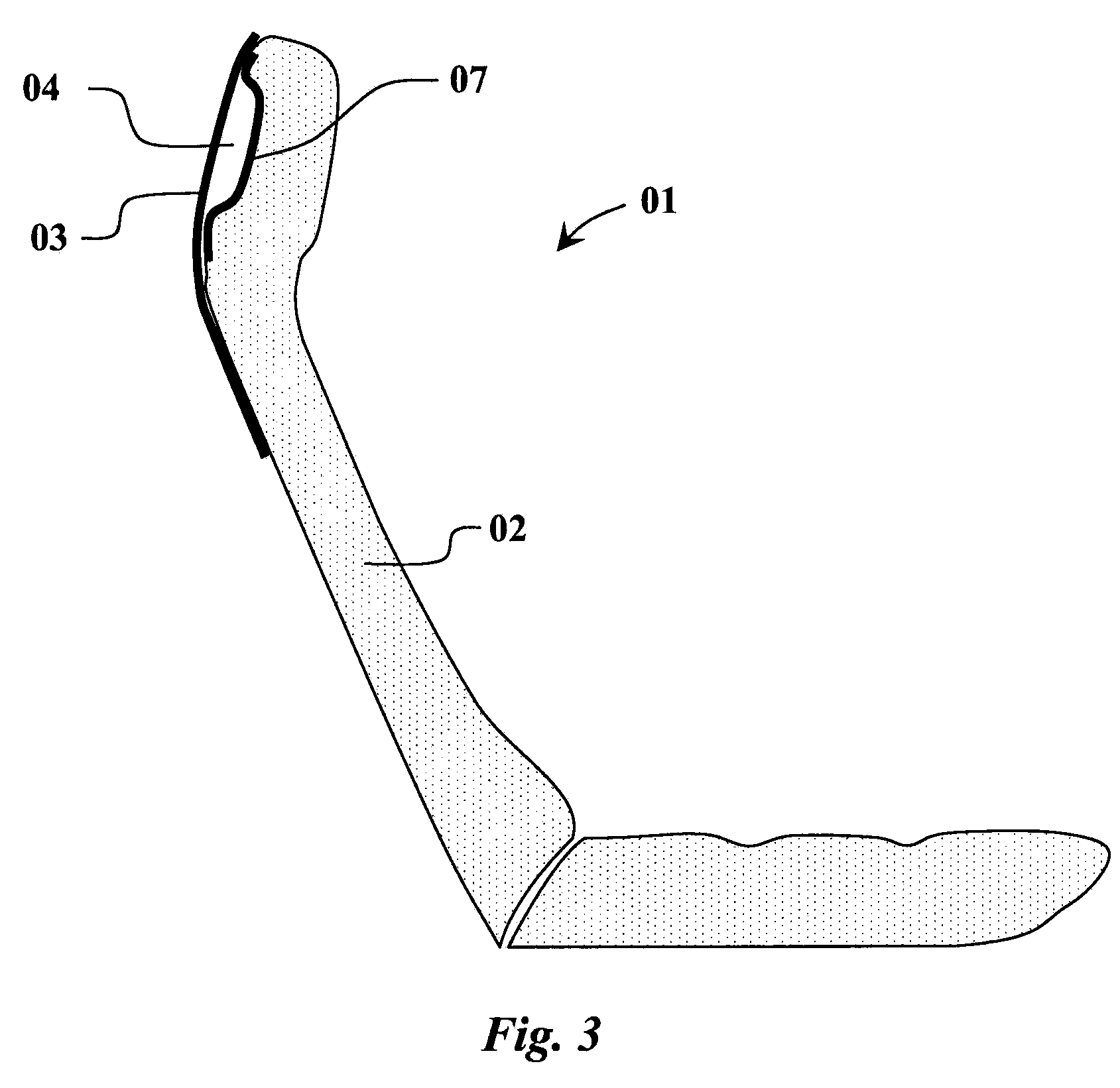
[0036]FIG. 1 shows an exemplary embodiment of a seat cushion 01 having a plurality of bubble elements 04. As is evident from this figure, first bubble elements 04a.1 and 04a.2 are disposed on both sides of the seat and are intended to provide the driver with improved lateral support. In the shoulder region, provision is further made for bubble elements 04b. Support in the region of the lumbar vertebrae is enabled with the aid of an additional bubble element 04c. By means of air conduits 10, bubble elements disposed in parallel are connected to one another. In this connection, these interconnected bubble elements are always simultaneously supplied with compressed air. The central air inlet 08 is laterally disposed on a lower side. This air inlet is guided towards a valve unit 09 from which the individual bubble elements can be supplied with compressed air.

[0037]The air inlet 08 having the valve unit 09 and the air conduits 10 forms the compressed air distribution system. This system ...


PUM


Abstract

A seat cushion for the production of a vehicle seat has a foam body and a carrier element. The carrier element is disposed on the back side of the foam body and provides mechanical support to the foam body on the back side thereof. At least one bubble element is disposed between the foam body and the carrier element and can be supplied with compressed air via an air inlet. The carrier element features an air-impermeable barrier layer on the side facing towards the foam body. The bubble element is composed of two bubble halves that are connected to one another by means of an airtight sealing joint, and wherein the bubble half facing away from the foam body is formed by a surface section of the barrier layer of the carrier element, and wherein the second bubble half facing towards the foam body is fastened at the assigned surface section of the barrier layer while forming the airtight sealing joint.

Description

CROSS REFERENCE TO RELATED APPLICATION[0001]This application claims priority to German Patent Application No. 10 2009 048 734.4, filed on Oct. 8, 2009, which is fully incorporated herein by reference.STATEMENT REGARDING FEDERALLY SPONSORED RESEARCH OR DEVELOPMENT[0002]Not applicable.FIELD OF THE INVENTION[0003]The present invention relates to a seat cushion having a foam body and a carrier element situated on the back side of the foam body, wherein a bubble element is disposed on the carrier element and is foamed into the foam body.BACKGROUND OF THE INVENTION[0004]To allow for enhanced seating comfort, in particular in vehicle seats the shape of the seat is varied by means of compressed-air-actuated bubble elements. Hence, individual adaptation of the seat contour to the respective person is rendered possible. Depending on the specific design, this function can additionally be used for massage purposes or for dynamical adaptation to driving situations.[0005]For this purpose, several...

Claims


Application Information

Patent Timeline
Patent Type & Authority Patents(United States)
IPC IPC(8): A47C7/34B60N2/90
CPCB60N2/7017B60N2/70B60N2/914
Inventor HOFMANN, MANFREDMECKELMANN, GUNTER
Owner FS FEHRER AUTOMOTIVE GMBH
Learn More