Transversal conduction lightning protection system

a technology of transverse conduction and protection system, which is applied in the direction of aircraft static dischargers, wind energy generation, liquid fuel engine components, etc., can solve the problems of composite material partial to total destruction, multiple unprotected blades damaged or destroyed, and long downtime of the facility

Active Publication Date: 2013-01-01
GENERAL ELECTRIC CO
View PDF10 Cites 29 Cited by
  • Summary
  • Abstract
  • Description
  • Claims
  • Application Information

AI Technical Summary

Benefits of technology

[0011]Briefly, in accordance with one embodiment, a lightning protection system (LPS) comprises a glass-reinforced fiber or carbon-reinforced wind turbine blade or aircraft wing comprising a tip region, a suction side, and a pressure side. A conductive or semi-conductive substantially planar element is disposed internal to the blade tip region or wing tip region and between the suction side and pressure side. The conductive or semi-conductive substantially planar element forces a pre-determined electric field distribution pattern or so-called electric field control region causing a lightning discharge to attach to the tip region. The conductive or semi-conductive substantially planar element is in electrical communication or galvanic connected with a conductive path such that the electric field control region and the conductive path together operate to protect the wind turbine blade or aircraft wing from damage due to a lightning strike in the tip region of the wind turbine blade or aircraft wing (airfoil) by controlling the electric field distribution in the tip region or entire blade caused by the lightning strike.

Problems solved by technology

Wind turbines are usually erected in open spaces or in more recent years at sea where they form the highest point and often attract lightning.
However, such blades are often covered by a thin layer of dust, salt or pollution and together with moisture, the risk of conducting a current is real and results in several unprotected blades being damaged or destroyed by lightning.
Their damage or destruction due to lightning results in the longest down-time of the facility.
Due to the limited number of receptors, there is a high probability that lightning strikes hit the blade between two receptors, leading to partial to total destruction of the composite material.
The processing step of including a metallic lattice into the lamination procedure however, makes later ones more complicated and can also increase the costs due to the higher material expenses.
In similar fashion, state-of-the-art lightning protection systems for aircraft wings (airfoils) make use of various forms of integration of a conductive path on the surface, e.g. a mesh, especially for composite material based wings, with the disadvantage that partial and local damage can be caused by the lightning attachment point.
The area close to the lightning attachment point for an airfoil can usually be damaged, which in some cases requires additional repairs after landing or at least an inspection.
This situation can result in more downtime of the aircraft and thus increases the operational costs and reduces the availability of the aircraft.

Method used


Image

  • Transversal conduction lightning protection system
  • Transversal conduction lightning protection system
  • Transversal conduction lightning protection system

Examples


Embodiment Construction

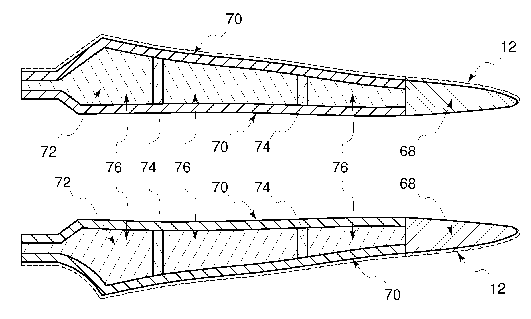
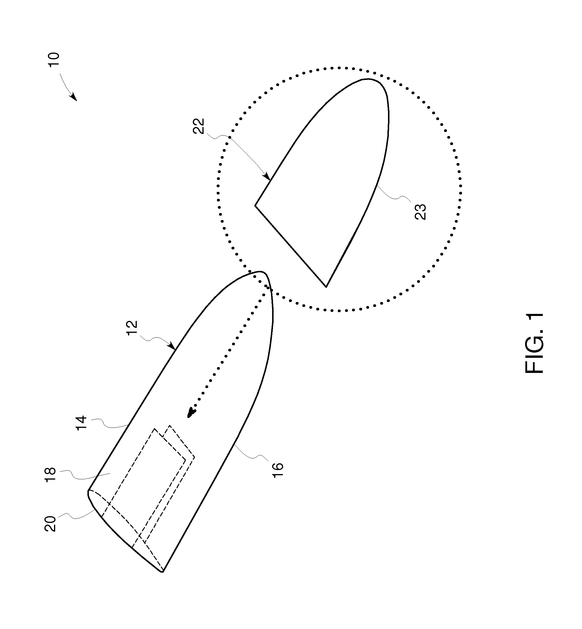
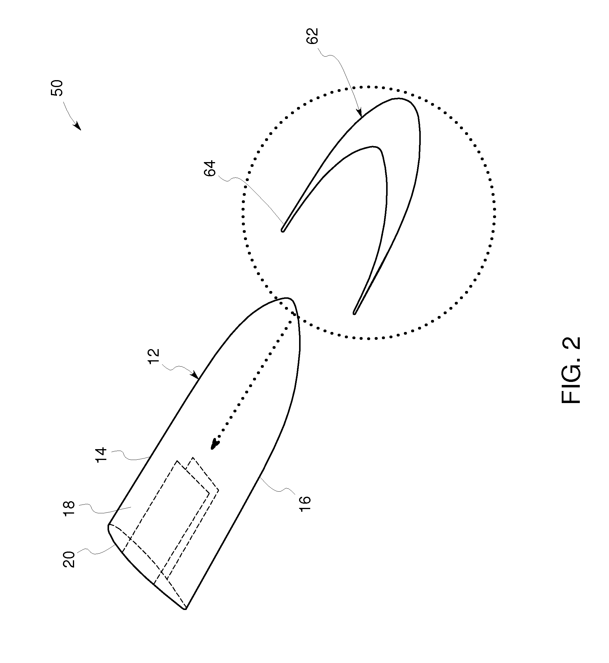
[0018]FIG. 1 illustrates a wind turbine blade tip lightning protection mechanism 10 according to one embodiment of the invention. One portion of lightning protection mechanism 10 includes a substantially flat sheet, mesh or foil of electrically conductive or semi-conductive material 22 disposed in a tip region 12 of a wind turbine blade or aircraft wing (airfoil). According to one aspect of the invention, the wind turbine blade or aircraft wing is constructed from a predetermined glass-reinforced fiber or carbon-reinforced material. The wind turbine blade or aircraft wing may also comprise a down conductor such as described in further detail below disposed on or integrated with the blade or wing.

[0019]Lightning protection mechanism 10 is easily adapted to rotor blades that have already been installed, so called retrofitting. One portion of the rotor blade or aircraft wing includes a tip region 12, a suction side 18, a pressure side 20, a leading edge 14 and a trailing edge 16. Accor...


PUM


Abstract

A lightning protection system for a wind turbine blade or aircraft wing includes a glass-reinforced fiber or carbon-reinforced wind turbine blade or aircraft wing having a tip region, a suction side, a pressure side, a leading edge and a trailing edge. A substantially planar sheet of conductive or semi-conductive material is disposed internal to the blade tip region or wing tip region and between the suction side and pressure side. The sheet operates during a lightning discharge to form an electric field control mechanism causing the lightning discharge to attach to the tip region. The sheet is in electrical communication or galvanic connection with a conductive or semi-conductive path such that the electric field control mechanism and the path together operate to protect the wind turbine blade or aircraft wing from damage caused by the lightning strike in the tip region of the wind turbine blade or aircraft wing by controlling an electric field in the tip region caused by the lightning strike.

Description

BACKGROUND[0001]The invention relates generally to lightning protection systems, and more specifically to a lightning protection system for wind turbine blades and aircraft wings (airfoils).[0002]A wide variety of lightning protection systems for protection of wind turbines and their associated blades are known within the art. Wind turbines are usually erected in open spaces or in more recent years at sea where they form the highest point and often attract lightning. The tips of the wind turbine blades reach the highest position and are therefore the usual place of impact for lightning.[0003]In the past, the fact that blades were often made of a non-conductive material such as glass fibre lead to the belief that lightning was not a problem. However, such blades are often covered by a thin layer of dust, salt or pollution and together with moisture, the risk of conducting a current is real and results in several unprotected blades being damaged or destroyed by lightning. Recent disco...

Claims


Application Information

Patent Timeline
Patent Type & Authority Patents(United States)
IPC IPC(8): F03D9/00
CPCF01D11/00F03D11/0033B64D45/02Y02T50/672Y02E10/722F03D80/30F05B2240/307Y02E10/72Y02T50/60
Inventor MENDEZ HERNANDEZ, YARU NAJEMROESNER, ROBERT
Owner GENERAL ELECTRIC CO
Why Eureka
Try Eureka